Thesis submitted in accordance with the requirements of the Universiti Teknikal Malaysia Melaka for the Bachelor Degree of Manufacturing Engineering
(Robotics and Automation) with Honours
By
Amirul Bin Sait
Faculty of Manufacturing Engineering May 2008
Potential Application of Ferrofluid for
Robot Gripping Mechanism
UTeM Library (Pind.1/2007)
UNIVERSITI TEKNIKAL MALAYSIA MELAKA
BORANG PENGESAHAN STATUS LAPORAN PSM
JUDUL:
POTENTIAL APPLICATION OF FERROFLUID FOR ROBOT GRIPPING MECHANISM
SESI PENGAJIAN: Semester 2 2007/2008
Saya Amirul Bin Sait
mengaku membenarkan laporan PSM / tesis (Sarjana/Doktor Falsafah) ini disimpan di Perpustakaan Universiti Teknikal Malaysia Melaka (UTeM) dengan syarat-syarat kegunaan seperti berikut:
1. Laporan PSM / tesis adalah hak milik Universiti Teknikal Malaysia Melaka dan
penulis.
2. Perpustakaan Universiti Teknikal Malaysia Melaka dibenarkan membuat salinan
untuk tujuan pengajian sahaja dengan izin penulis.
3. Perpustakaan dibenarkan membuat salinan laporan PSM / tesis ini sebagai bahan
pertukaran antara institusi pengajian tinggi.
4. *Sila tandakan (√)
SULIT
TERHAD
TIDAK TERHAD
(Mengandungi maklumat yang berdarjah keselamatan atau kepentingan Malaysia yang termaktub di dalam AKTA RAHSIA RASMI 1972)
(Mengandungi maklumat TERHAD yang telah ditentukan oleh organisasi/badan di mana penyelidikan dijalankan)
(TANDATANGAN PENULIS) Alamat Tetap:
NO 53 TMN PUTERI, LRG CAHYA INDAH 1, JLN SULTAN TGH, 93050,
PETRA JAYA, SARAWAK.
Tarikh: _______________________
(TANDATANGAN PENYELIA)
Cop Rasmi:
Tarikh: _______________________
APPROVAL
This report is submitted to the Faculty of Manufacturing Engineering of UTeM as a partial fulfillment of the requirements for the degree of Bachelor of Manufacturing
Engineering (Robotics and Automation) with Honours. The members of the supervisory committee are as follow:
Muhamad Arfauz Bin A. Rahman (PSM Supervisor)
DECLARATION
I hereby declare that this report entitled “Potential application of Ferrofluid for Robot Gripping Mechanism” is the result of my own research except as cited in the
references.
Signature :
Author’s Name : AMIRUL BIN SAIT
i
ABSTRACT
ii
ABSTRAK
iii
DEDICATION
iv
ACKNOWLEDGEMENTS
ix
LIST OF FIGURES
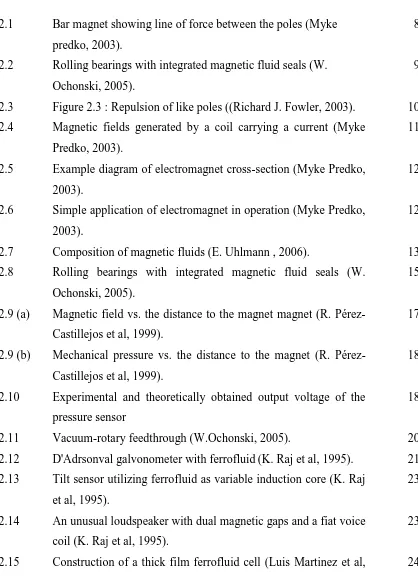
2.1 Bar magnet showing line of force between the poles (Myke predko, 2003).
8
2.2 Rolling bearings with integrated magnetic fluid seals (W. Ochonski, 2005).
9
2.3 Figure 2.3 : Repulsion of like poles ((Richard J. Fowler, 2003). 10 2.4 Magnetic fields generated by a coil carrying a current (Myke
Predko, 2003).
11
2.5 Example diagram of electromagnet cross-section (Myke Predko, 2003).
12
2.6 Simple application of electromagnet in operation (Myke Predko, 2003).
12
2.7 Composition of magnetic fluids (E. Uhlmann , 2006). 13 2.8 Rolling bearings with integrated magnetic fluid seals (W.
Ochonski, 2005).
15
2.9 (a) Magnetic field vs. the distance to the magnet magnet (R. Pérez-Castillejos et al, 1999).
17
2.9 (b) Mechanical pressure vs. the distance to the magnet (R. Pérez-Castillejos et al, 1999).
18
2.10 Experimental and theoretically obtained output voltage of the pressure sensor
18
2.11 Vacuum-rotary feedthrough (W.Ochonski, 2005). 20
2.12 D'Adrsonval galvonometer with ferrofluid(K. Raj et al, 1995). 21 2.13 Tilt sensor utilizing ferrofluid as variable induction core (K. Raj
et al, 1995).
23
2.14 An unusual loudspeaker with dual magnetic gaps and a fiat voice coil (K. Raj et al, 1995).
23
x 2005).
2.16 Optical system for estimation of Verdet constant (Luis Martinez et al, 2005).
25
2.17 Ferrofluid fixed with a permanent magnet. 26
2.18 Principle and experimental set-up of a one-axis system with scattered (I) and optimized magnetic field (II) (E. Uhlmann & N. Bayat, 2004)
27
2.19 Load capacity of the one-axis positioning system for different ferrofluids and volume of fluid.
28
2.20 Principle and prototype of a miniaturized multidimensional one-axis positioning system.
28
2.21 Actor cases (at the top) and experimental set-up of multi-axis positioning systems (below at the right) (E. Uhlmann & N. Bayat, 2004).
29
3.1 (a) Flow Chart of the robot gripping mechanism process 32 3.1 (b) Flow Chart of the robot gripping mechanism process 33
3.2 The step of concept generation method. 34
3.3 Overall “black box”. 36
3.4 Refinement showing subfunctions 37
3.5 Flow chart for the replication of the robot gripper 42 3.6 Influences on the load capacity of the magnetofluidic
positioning system (E. Uhlmann & N. Bayat, 2003)
43
4.5 3 Dimensional drawing using Solidworks software 52
4.6 Polygon Cube tool 53
xi
4.8 Wireframe of the robot gripper 54
4.9 Shaded modeling diagram 54
4.10 Animation keyframe 55
4.11 Initial position of the designed robot gripper 56
4.12 Gripping position of the robot gripper 57
4.13 Final simulation of the robot gripper 57
4.14 The replication of the robot gripper 60
5.1 The replication cross-sectional diagram 61
5.2 The load versus spring displacement graph. 64
5.3 Load characteristic with the Cobalt Based Ferrofluid (E. Uhlmann & N. Bayat, 2003)
66
5.4 Connection of the circuit 67
xii
LIST OF TABLES
2.1 Gripper classification according to their physical principle of
operation (Gareth J. Monkman et al, 2007) 7
2.2 Gripper classification and suitability of object materials (Gareth J.
Monkman et al, 2007) 7
2.3 Carriers in the commercial ferrofluid (K. Raj et al, 1995)
16 2.4 Thermal stabilities of successive generations of ferrofluids. Equal
amounts of ferrofluids are exposed to 175°C in dishes until the fluids congeal. The number of hours represent the relative thermal
stability (K. Raj et al, 1995) 16
2.5 Properties of a thick film ferrofluid cell (Luis Martinez et al, 2005) 25 4.1 The screening matrix for the conceptual design of the robot gripping
mechanism 51
4.2 The manufacturing process involve 58
xiii
LIST OF ABBREVIATIONS, SYMBOLS, SPECIALIZED
NOMENCLATURE
nm - nanometer
µm - micronmeter
2D - Two Dimensional
CAD - Computer Aided Manufacturing
1
CHAPTER 1
INTRODUCTION
1.1 INTRODUCTION
Materials that are attracted by magnetic fields are called magnetic materials (Robert J. Fowler, 2003). The most common magnetic materials are iron, iron compound and alloys containing iron or steel (Robert J. Fowler, 2003). These magnetic materials are also called ferro magnetic materials as ferro is a prefix that means iron. In general, ferrofluid is magnetic iron in liquid form. Electricity and magnetism cannot be separated as magnetism created by an electric current. It is known that an electric current produces a magnetic field (Robert J. Fowler, 2003). The main application areas which is sealing, damping and heat transfer, continue to dominate the commercial activities but in each category new market opportunities have resulted in the development of mechanical devices and ferrofluids. There is now an increased use of ferrofluids in stepper motors, and D'Arsonval meters are at the stage of testing. In both cases one of the objectives is to damp the system and improve product performance. Transducer have become more importance of the magnetic fluids and, as a result, new sensor products are now in the manufacturing field.
2
magnetic drug targeting (MDT), magnetic hyperthermia (MHT) and artificial heart and
muscles (Uhlmann, 2006). Biomedical applications focus on the single colloids’
properties. While in technical applications there are more on product and process application likes loud speaker, lubricants, and seals in feed-through, cooling, sensors and
damping medium (E. Uhlmann, 2006). Technical applications consider the ferrofluids’
properties as a whole fluid described by its magnetorheological behavior, magnetization and permeability for magnetic forces. In positioning applications, it still less applies.
Magnetic fluid also called ferrofluid (W. Ochonski, 2005), consist magnetic particles that able to react with magnetic field. Ferro fluids respond immediately to changes in applied magnetic field and removing the field quickly randomize the moment (W. Ochonski, 2005). It explains that the ferrofluid is compliance and we can manipulate it according to the wanted current. The magnetic field can be controlled as known magnetic field move from north to the south. In order to develop the robot gripper, it requires movement and force. Here, ferrofluid will be used as an active medium for generating a variable magnetic force which will acts on actor and enables the movement (E. Uhlmann & N. Bayat, 2004). The magnetic force will be produced from the movement of the ferrofluid that can be control by the current through the coil installed. Using a permanent magnet also can produce a magnetic field, however, coil is better as the concentration of the magnetic field can be manipulate. As a result, it will transmit the force to the actor of the robot gripper.
3
1.2 PROBLEM STATEMENT
Using electrical supply is one of the common for developing a robot gripper. However, the danger of electrical sparks, non-direct drive motors are geared down and can cause such problems as backlash, friction, compliance and wear which can affect the accuracy and repeatability of the robot (James W. Masterson et al, 1996).Hydraulics can supply large amount of instant power and provide precise motion over a wide range of speeds but it is expensive to purchase and maintain. It is not energy efficient and noisier than electrical units and due to fluid leaks, they are not recommended for clean room environments (James W. Masterson et al, 1996).Pneumatics works at high speeds and is economical to operate and maintain. The disadvantage is air is compressible, making precise placement and positioning more difficult to control. It is difficult to keep air used by pneumatic system clean and dry and noisier than either electrical or hydraulic systems (James W. Masterson et al, 1996). With the use of the ferrofluid, this new technological application can reduce the noise, as the ferrofluid is reflect only with generated coil. Besides, the large amount of power can be produce and provide precise motion.
1.3 OBJECTIVE
To analyze and evaluate the potential application of ferrofluid in robot gripping mechanism.
To design and develop a replication of a suitable robot gripping mechanism.
1.4 SCOPE
To collect, analyze and evaluate the relevant information regarding to the ferrofluid application from previous and current research.
4
1.5 BENEFIT
5
CHAPTER 2
LITERATURE REVIEW
2.1 ROBOT GRIPPER
Gripper is considered as a subsystem of a handling mechanism which provides temporary contact with the object to be grasped (Gareth J. Monkman et al, 2007). From the definition, we can understand that operation of the gripper is grasping an object.
However, the term “gripper” is also used in cases where no actual grasping, but rather
holding an object, for example in vacuum suction where the force can act on a material. There are many gripper can be found in industry and their functions is depend on the specific application. According to the Gareth J. Monkman et al, their function can be as following ;
(a) Temporary maintenance of a definite position and orientation of the workpiece relative to the gripper and handling equipment.
(b) Retaining of static (weight), dynamic (motion, acceleration or deceleration) or process specific force and moments.
(c) Determination and change of position and orientation of the object relative to the handling equipment by means of wrist axes.
(d) Specific technical operations performed with, or in conjunction with the gripper.
6
2.2 ROBOT GRIPPER CLASSIFICATION
One should differentiate between grasping (prehension) and holding (retention) forces. This is important as these are the most used type of gripper in industry. The grasping force is applied at the initial point of prehension (during the grasping process), while the holding force maintains the grip thereafter (until object release) (Gareth J. Monkman et al, 2007). In general, the retention force may be weaker than the prehension force. This is because the grasping force is determined by the energy required from the mechanical motion. Robot grippers may be categorized in broadest manner. Fan Yu Chen (1982) classified gripper into three types which is mechanical finger, vacuum and magnetic, and universal grippers.
7
Table 2.1 : Gripper classification according to their physical principle of operation (Gareth J. Monkman et al, 2007)
Prehension
method Gripper type Typical object materials
Impactive Rigid objects
Ingresive Intrusive Flexible Objects : textiles, carbon and glass fibre Non-intrusive Flexible Objects : textiles, carbon and glass fibre
Vacuum suction Non-porous, rigid materials
Astrictive Magnetoadhesion Ferrous materials
Electroadhesion Light sheet materials and microcomponents
Thermal Flexible Objects : textiles, carbon and glass fibre
Contigutive Chemical Carbon fibre with glue impregnation
Fluid Small, light objects (microcomponents)
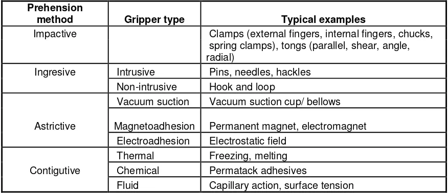
Table 2.2 : Gripper classification and suitability of object materials (Gareth J. Monkman et al, 2007)
Prehension
method Gripper type Typical examples
Impactive Clamps (external fingers, internal fingers, chucks,
spring clamps), tongs (parallel, shear, angle, radial)
Ingresive Intrusive Pins, needles, hackles
Non-intrusive Hook and loop
Vacuum suction Vacuum suction cup/ bellows
Astrictive Magnetoadhesion Permanent magnet, electromagnet
Electroadhesion Electrostatic field
Thermal Freezing, melting
Contigutive Chemical Permatack adhesives