DEVELOPMENT OF AN AUTOMOTIVE CLUTCH ACTUATOR USING SHAPE MEMORY ALLOY (SMA) MATERIAL
MOHAMMAD FITRI BIN MOHAMED RIDZUAN
This report is submitted in partial fulfillment of the requirement for the Bachelor of Mechanical Engineering (Automotive)
Faculty of Mechanical Engineering Universiti Teknikal Malaysia Melaka
ii
SUPERVISOR DECLARATION
“I hereby declare that I have read this thesis and in my opinion this report is sufficient in terms of scope and quality for the award of the degree of
Bachelor of Mechanical Engineering (Automotive)”
Signature : ……… Supervisor I : Mr. Herdy Rusnandi
Date : ………....
Signature : ………
Supervisor II : ………
iii
DECLARATION
“I hereby declare that the work in this report is my own except for summaries and quotations which have been duly acknowledged.”
iv
ACKNOWLEDGEMENT
First, I would like to express my greatest gratitude to Almighty Allah for giving me a chance to complete my project with all His blessings. I would like to acknowledge my project supervisor, Mr. Herdy Rusnandi. The fundamental idea of this project is his and he was a valuable source of information about this project. I am very thankful that he supervised my work and provided me with the much needed assistance in understanding the project. Without his guidance and support, I may not be able to achieve the goals of this project.
v
ABSTRACT
vi
ABSTRAK
vii
CONTENT
CHAPTER SUBJECT PAGE
DECLARATION ii
ACKNOWLEDGEMENT iv
ABSTRACT v
ABSTRAK vi
CONTENT vii
LIST OF FIGURE ix
LIST OF APPENDIX xi
CHAPTER 1 INTRODUCTION
1.1 Background 1
1.2 Problem Statement 10
1.3 Objectives 11
1.4 Scope 11
CHAPTER 2 LITERATURE REVIEW
2.1 Shape Memory Alloy 12
2.2 Automotive Clutch 17
2.2.1 Clutch Fork 20
viii
CHAPTER SUBJECT PAGE
2.2.3 Pressure Plate Cluch Housing 22 2.2.4 Coil Spring Pressure Plate 23
2.2.5 Clutch Disc 25
2.2.6 Flywheel 26
2.2.7 Pilot Bearing 26
2.3 Clutch Operation 27
CHAPTER 3 METHODOLOGY
3.1 Background 28
3.2 Engineering Design Process 30
3.2.1 Identify The Problem 31
3.2.2 Identify Criteria and Constraint 31 3.2.3 Brainstorm Possible Solution 31
3.2.4 Generate Ideas 32
3.2.5 Explore Possibilities 35
3.2.6 Selected Design 37
3.2.7 Calculation 38
3.2.8 Build a Model or Prototype 42
3.2.9 Refine The Design 43
3.3 Circuit 44
3.4 Operation of SMA clutch actuator 45 3.5 Application of SMA clutch actuator 46
CHAPTER 4 RESULT AND DISCUSSION
4.1 Background 47
4.2 Result 47
ix
CHAPTER 5 CONCLUSION AND RECOMMENDATION
5.1 Conclusion 51
5.2 Recommendation 51
REFERENCE 52
BIBLIOGRAPHY 54
x
LIST OF FIGURE
FIGURE TITLE PAGE
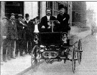
1.1 George B. Selden, In Car Powered By
His Original Engine Built In 1877 1
1.2 Panhard & Levassor first design 2
1.3 Celebrities rolled into Panhard et Levassor Louis
Pasteur left (car 1899) and Claude Monet right (car 1901) 3
1.4 Sliding gear transmission 4
1.5 Reo Self-Shifter 6
1.6 Dynaflow 7
1.7 Chevrolet Powerglide 8
1.8 Fordomatic 8
1.9 Hydraulic Clutch Linkage 10
2.1 SMA Actuator Using Rigid Element 13
2.2 Nitinol Muscle Wire 14
2.3 Transformation from austenite to martensite phase and shape
memory effect 14
2.4 Graph of Length versus Temperature for Shape Memory Alloy 15
2.5 Graph of Resistance Value versus Temperature 16
2.6 Single disc clutch 17
2.7 Double disc clutch exploded view 18
2.8 Clutch linkage mechanism 19
2.9 Clutch cable mechanism 19
2.10 Hydraulic clutch release mechanism 20
2.11 Hydraulic clutch release mechanism 21
xi
FIGURE TITLE PAGE
2.13 Coil spring pressure plate 24
2.14 Diaphragm pressure plate operation 24
2.15 Clutch operation 27
3.1 Flow Chart Of Final Year Project 29
3.2 Engineering Design Process 30
3.3 Activate Clutch Using Clutch Paddle 32
3.4 Activate Clutch Using Hand Paddle 32
3.5 Simulation of SMA Actuator Design 1 inside Clutch 33 3.6 Simulation of SMA Actuator Design 2 inside Clutch 34
3.7 1st design drawing 35
3.8 2nd design drawing 36
3.9 Motorcycle clutch 39
3.10 Clutch displacement 39
3.11 First design prototype 42
3.12 Second design prototype 42
3.13 Schematic diagram of the circuit 44
3.14 Variable resistor 45
3.15 Conventional clutch controller 46
3.16 Proposed clutch controller 46
4.1 Graph of voltage versus activation time 48
xii
LIST OF TABLE
TABLE TITLE PAGE
1 Evaluation of the Design 37
2 SMA properties 40
3 First design actuator performance 43
4 Second design actuator performance 43
5 First design actuator performance 48
xiii
LIST OF APPENDIX
APPENDIX TITLE PAGE
Appendix A Gantt Chart PSM 1 59
1
CHAPTER 1
INTRODUCTION
1.1 BACKGROUND
Getting power from the engine to the wheels of an automobile has provided a seemingly endless challenge for rear-wheel-drive, front-wheel-drive, 4-wheel-drive, front-engine, rear-engine, and mid-engine cars, longitudinal, transverse, vertical, slant, and flat engines, plus an amazing array of hardware in between. George Selden's notorious 1877 patent was for a front-drive carriage with a transverse 3-cylinder engine, anticipating the Chevy/Suzuki Sprint by over a century. When it comes to car designs, there are very few new ideas, just progressively successful adaptations of old concepts.
2
The heart of the drive train is the transmission. Because gasoline engines develop their torque over a very narrow speed range, several gears are needed to reach useful road speeds.
The modern transmission was introduced by a pair of Frenchmen, Louis-Rene Panhard and Emile Levassor in 1894. The engineers had invited the press to a demonstration of "the most revolutionary advancement to date in the brief history of the motor car industry." Unfortunately, the engine in their demo vehicle died, and they were reduced to giving a chalk talk on multi-geared transmission theory to a bored press corps.
Figure 1.2: Panhard & Levassor first design (Source: www.jalopyjournal.com)
3
Thus, British auto pioneer F. W. Lanchester describes the transmissions in his cars: "One belt-driven HIGH gear that will go over everything and one belt-driven LOW gear in case the car had to climb a tree."
It was not until a year after their disastrous news conference that Panhard and Levassor regained their reputations. At this time, they had their first car ready for the press to drive. With it, they changed a lot of minds.
Figure 1.3: Celebrities rolled into Panhard et Levassor Louis Pasteur left (car 1899) and Claude Monet right (car 1901)
(Source: www.svvs.org/help01.shtml)
4
The live rear axle which Renault adapted from an idea developed in 1893 by an American, C. E. Duryea was called the differential rear axle. It used a number of gears to overcome the problem of rapid tire wear, which resulted on turns with the "dead" axles used by all other carmakers. "Differential" referred to the ability of the unit to turn the outer driving wheel faster than the inner driving wheel, eliminating tire scuffing in turns.
By 1904, the Panhard-Levassor sliding gear manual transmission had been adopted by most carmakers. In one form or another, it has remained in use until recent times. Obviously, there have been improvements, the most significant being the invention of a synchronizing system that permits drive and driven gears to be brought into mesh with each other smoothly without gear clashing. This system allows both sets of gears to reach the same speed before they are engaged. The first of these synchromesh transmissions was introduced by Cadillac in 1928. An improvement to the design patented by Porsche is widely used today.
Between the time the sliding gear-transmission was introduced and the perfection of the synchromesh, there were other attempts at making it easier for the driver to shift gears. One was the planetary transmission in the 1908 Model T Ford. It had a central gear, called the "sun" gear, surrounded by three "planet" gears. Today, planetary gears are more widely used in automatic transmissions than in manual.
Figure 1.4: Sliding gear transmission
5
Some pretty elaborate planetary manual transmissions did evolve, however. One was developed by Walter Wilson and was called the Wilson Preselector. It came along in 1930.
This gear system, which used four individual planetary gear sets, allowed the driver to preselect one gear ratio by moving a small lever on the steering column. the driver could then "order up" the particular preselected gear by depressing a foot pedal. This caused a camshaft to disengage one gear and simultaneously allow the preselected gear set to engage.
All transmission designs since the Panhard-Levassor unit have had one goal in common to make shifting easier. Obviously, the easiest to shift transmission is the automatic. It's strictly an American innovation.
The first automatic was invented in 1904 by the Sturtevant brothers of Boston. It provided two forward speeds that were engaged and disengaged by the action of centrifugal weights without need for a foot-operated clutch. As engine speed increased, the weights swung out to engage bands first the low-gear band and then the high-gear band. The unit failed because the weights often flew apart.
6
Figure 1.5: Reo Self-Shifter
(Source: www.kitfoster.com/archive/2007_02_01_archive.html)
7
The Hydra-Matic consisted of three planetary gear sets that were operated hydraulically. A fluid coupling was used to connect the engine and transmission. Credit for perfecting the fluid coupling goes to Chrysler, which developed the concept in 1937. However, Chrysler did not make use of it until 1941, when the Chrysler Fluid Drive transmission was introduced. This was not an automatic unit, but a standard transmission with a fluid coupling, not a clutch.
By 1948, the automatic transmission had evolved into the hydraulic torque converter that we know today coupled to a planetary gear train. The first to use the converter was Buick. In 1948 Buick offered the Dynaflow fully automatic transmission on the Roadmaster. Within three years, 85 percent of Buicks had the Dynaflow. The Dynaflow was the model for present-day automatic transmissions. Others soon followed with similar units Chevrolet Powerglide, Fordomatic and Merc-O-Matic in 1950; and the Chrysler M-6 Torque Converter Automatic in 1951.
Figure 1.6: Dynaflow
8
Figure 1.7: Chevrolet Powerglide
(Source: www.51classicchevy.com/1951-six-cylinder-engines.html)
Figure 1.8 : Fordomatic
(Source: www.crankshaftcoalition.com/wiki/Transmission_identification)
These are some other interesting developments in the history of transmissions and drive units.
9
Universal joints were first introduced on the 1902 Peerless. The 1908 Franklin was the first car to use roller-bearing U-joints. The 1930 Hupmobile pioneered needle-bearing U-joints, which is the point where we stand today.
Although differential locks were first used on a steam lorry in 1903 to provide wheel traction on slippery roads, it was not until 1956 that the first production limited-slip differential for a popular car was produced by Studebaker.
In 1906, Otto Zachow and William Besserdich of Clintonville, Wisconsin, built a car with the first successful 4-wheel-drive unit. A year later, they began a company called the Four Wheel Drive Auto Co.
In 1913, Packard made a milestone step in differential development with the introduction of a spiral-bevel ring and pinion set that cut the noise level produced in the rear axle. In 1926, with the introduction by Packard of the hypoid gear rear axle, noise ceased to be a problem altogether, unless the differential was going bad.
In 1934, automatic overdrive was introduced on the Chrysler and DeSoto Airflow.
10
1.2 PROBLEM STATEMENT
Many late model vehicles have a hydraulic clutch linkage with a master cylinder attached to the clutch pedal and slave cylinder on the bell housing. The internal piston seals on the master and slave cylinder can develop leaks that allow a loss of pressure when the clutch pedal is depressed. This may prevent the clutch from disengaging or allow it to engage prematurely.
Figure 1.9: Hydraulic Clutch Linkage
(Source: www.autopartslib.com/2010/01/20/car/fiat-uno-hydraulic-clutch-components-assembly-and-parts-diagram)
11
1.3 OBJECTIVES
To design and develop an automotive clutch actuator using shape memory alloy material.
1.4 SCOPES
a) To study mechanical behavior of shape memory alloy (SMA) for actuator application.
b) To design and develop a prototype of an automotive clutch actuator using SMA material.