8
CHAPTER 2
LITERATURE REVIEW
Recent advances in civil structures such as high rise buildings, towers and long span bridges go with an additional flexibility and insufficient inherent damping, which lead to an increase in their susceptibility to external excitation. Therefore, these flexible structures are susceptible to be exposed to excessive levels of vibration under the the actions of a strong wind or earthquake. The protection of such structures from natural hazards puts an important task for engineers and researchers. To ensure the functional performance of flexible structures against such undesirable vibrations, various design alternatives have been developed, ranging from alternatives structural systems to modern control systems with the use of various types of control devices. In general, we could classify modern control, namely passive, active, semi active and hybrid (Azar et al.,2010).
Among these modern control systems, the semi active approach has recently received considerable attention, because it offers significant adaptability without large power requirements. Actually, semi active control systems are consisted of improved passive devices which have controllable dynamic properties that alter at any moment according to the feedback or feedforward data to achieve an optimal performance. One of the example of semi active device uses controllable fluids. The advantage of controllable fluid device is that they contain no moving parts other than the piston, which makes them very reliable (dyke 1996).
Two fluids that are viable contenders for development of controllable dampers are (i) electrorheological (ER) fluids and (ii) magnetorheological (MR) fluids. The essential characteristic of controllable fluids is their ability to reversibly change from a free-flowing,
9
10
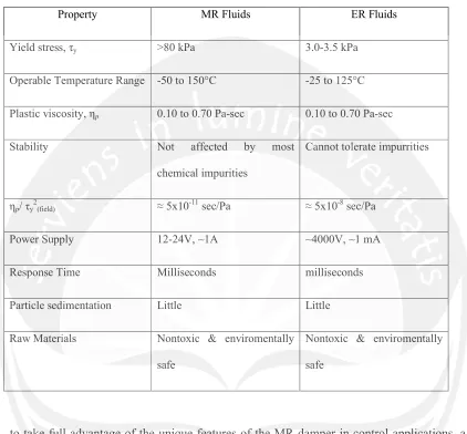
Table 1.1 Summary of the Physical Characteristic of MR and ER Fluids
(Dyke, 1996)
Property MR Fluids ER Fluids
Yield stress, τy >80 kPa 3.0-3.5 kPa
Operable Temperature Range -50 to 150°C -25 to 125°C
Plastic viscosity, ηp 0.10 to 0.70 Pa-sec 0.10 to 0.70 Pa-sec
Stability Not affected by most
chemical impurities
Cannot tolerate impurrities
ηp/ τy2(field) ≈ 5x10-11sec/Pa ≈ 5x10⁻⁸sec/Pa
Power Supply 12-24V, ~1A ~4000V, ~1 mA
Response Time Milliseconds milliseconds
Particle sedimentation Little Little
Raw Materials Nontoxic & enviromentally
safe
Nontoxic & enviromentally
safe
11
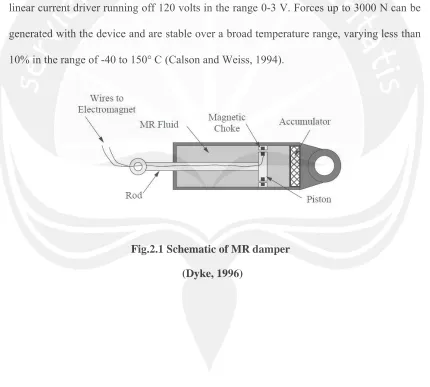
[image:4.612.97.527.274.661.2]fluid and the damper has a ± 2.5 cm stroke. As shown in Fig. 2.1, the MR fluid valve is contained within the damper piston and consists of an annular flow channel having an inner diameter of 27 mm and an outer diameter of 28 mm. the magnetic field is applied radially across the resulting 0.5mm dimension, perpendicular to the direction of fluid flow. The magnetic field can be varied from 0 to 200 kA/m for currents of 0 to 1 amp in the electromagnet coil, which has a resistance of 4 Ω. The peak power is less than 10 watts, which would allow the damper to be operated continously for more than an hour on a small camera battery. For this example, the current for the electromagnet is supplied by a linear current driver running off 120 volts in the range 0-3 V. Forces up to 3000 N can be generated with the device and are stable over a broad temperature range, varying less than 10% in the range of -40 to 150° C (Calson and Weiss, 1994).