Faculty of Engineering, University of Indonesia, Depok 16424
e-mail: [email protected], [email protected], [email protected], [email protected]
Abstrak
Konverter penaik tegangan (Boost Converter) merupakan peralatan yang penting dalam sistem jaringan listrik mikro arus searah (DC microgrid) yang berfungsi sebagai penaik tegangan. Dalam pembuatan boost converter peralatan pembangkit daya sering mengalami persoalan tersendiri terutama dalam perancangan transformator switching sehingga membutuhkan waktu yang lama dan biaya yang mahal. Untuk mengatasi persoalan tersebut dalam penelitian ini telah dibuat pengembangan inverter sebagai boost converter yang dilakukan secara simulasi dan experimen. Hasil simulasi menunjukan bahwa untuk tegangan masukan 10-14 Vdc mengasilkan tegangan 254 Vdc, sedangkan melalui pengukuran untuk tegangan masukan 10-14 Vdc menghasilkan tegangan 253 Vdc. Baik hasil simulasi maupun hasil pengukuran menunjukan bahwa tegangan tersebut dapat diterapkan dalam sistim jaringan listrik mikro arus searah untuk keperluan beban berbasic adaptor swiching (switch mode power supply/SMPS).
Kata kunci: jaringan listrik, jaringan listrik mikro arus searah, inverter, penaik tegangan
Abstract
DC boost converter is an essensial equipment in the system of DC microgrid which has a function as step up voltage. In making a boost converter equipment of power generation, it often encounters a problem within especially in designing of switching transformer, so that it is need a long development time and high development cost. In order to solve this problem, in this research it has been made a inverter development as boost converter which has been done by simulation and experiment. The simulation results show that for an input voltage 10-14 Vdc yields voltage 254 Vdc, while by testing for an input voltage 10-14 Vdc yields voltage 253 Vdc. Either simulation or test result show that voltage can be applied in the system of dc micro grid for the need of load based switch mode power supply /SMPS.
Keywords: microgrid, dc microgrid, converter, inverter, boost converter
1. Introduction
The concept of microgrid network is first developed by RH. Lassete in 2002, that is a pattern of distributed generation covering variety of energy sources from fossil energy sources to renewable energy sources (solar, wind and biogas). Microgrid is a network system interconnected from variety of distributed energy sources into a little network which can be operated independently or connected to utility grid [1][2]. Figure 1 shows the concept of microgrid supplied by some renewable energy sources and connected to utility grid.
Figure 1. Concept of Microgrid [3]
Research about DC microgrid started developing by Youichi Ito in 2004 [7]. The DC microgrid is developed to meet the need of increased electric power coincides with developing microgrid system. The microgrid is economic if it is used for supplying electric power in an isolated region such as mountainous areas and remote areas. The DC microgrid can eliminate DC-AC converter or AC to DC converter, so that it will get high efficiency with low cost and short length of line. The dc microgrid can supply a load switch mode power supply/SMPS which can operate at the voltage of 100-240 Vac or 141-340 Vdc [8]
.
Most of environmental friendly generators use dc sources. It is eminently suitable and electronic and digital equipments using direct current. The network system of dc microgrid is built as well as the existing electric power system.The microgrid system consists of [9]: a. Power generation or distributed generation b. Converter
c. Load
d. Energy storage unit
e. Transmission / distribution line
f. Control system and communication line
The dc microgrid diagram can be seen in Figure 2.
Figure 2. DC Microgrid Diagram [9]
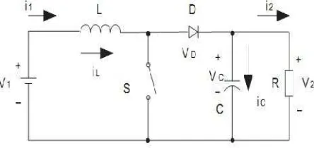
Figure 3. Circuit diagram of boost converter
The output voltage of boost converter can be calculated using equation below:
=
=
... (1)Where:
T = periode of wave, T = f = chopping frequency ton= time of switch on
k = repeatedly conduction cycle, k =
Piotr Biezel explains using boost converter in the dc requires criterion as follows [11] : a. Ripple current at low input and output
b. Having high abilities to switching over voltage c. Controllable from external
d. High efficiency e. Low cost
Research about conventer in the dc microgrid has been carried out by P. Biczel,. 2007. This research explains a role of dc converter in the dc microgrid to change from one level voltage to another level voltage. This equipment is needed in order to voltage suplying the microgrid meets the voltage needed. Several development methods DC-DC converter have been done in order to get higher efficiency using swicthed-capacitor circuit or the other [12]. In 2010 Yi-Ping also performed a research about increasing the efficiency in dc converter with electronic circuit variations such as capacitor, diode and inductor by performing installation configurations in order to get higher efficiency [13]. Felinto S.F,Silva, Antonio A.A., et al., have developed high gain DC-DC boost converter with a coupling inductor in a solar cell. This research explains about a model of step up voltage from 24 V dc to 311 V [14].
2. Research Method
Performed research method uses simulation and experiment.
2.1. Simulation Method
In the simulation method, test circuit is taken from circuit of Matlab Simulink DC boost converter by determining initially input parameters needed:
Parameter.1.
Determining average output current at the edge of continuous conduction in boost converter is given by equation : [16]
After determining parameter 1, obtained values of 1. Calculation ofduty cycle(D)
2. Calculation of inductance 3. Calculation of capacitance
From those results than are entered to Matlab Simulink in order to know the output voltage obtained. Simulation circuit for DC boost converter can be seen in Figure 4.
2.2. Experiment Method
Figure 4. Simulation of DC Boost Converter with PID
Figure 5. The Scheme of Development of Inverter as DC Boost Converter.
Test of inverter as DC boost Converter is performed by feeding input voltage (Vs ) from a variable power supply 3 A, Varying the supply voltage from 10 Volt to 14 Volt, the output voltage from DC boost converter resulted is compared with simulation results. Figure 6 shows the experiment of inverter as DC boost converter. The implementation of development of inverter as DC boost converter in the DC microgrid can be seen in Figure 7.
Figure 6 . Development of Inverter as DC Boost Converter
Figure 7. Implementation of Boost Converter in DC Microgrid
3. Results and Analysis
appliances with a model ofswitch mode power supplay/SMPS operating in the range of voltage 100 – 240 Vac [17]
3.1. Simulation Results
Using simulation of Matlab Simulink by input parameter data 1 and equation (2) and (3), than the results can be obtained in Figure 8.
Vs = 10 Vdc Vo = 254 Vdc
Vs = 12 Vdc Vo = 254 Vdc
Vs = 14 Vdc Vo = 254 Vdc
Figure 8. The graph of input voltage (Vs) vs output voltage (Vo) in the development of Inverter as DC Boost Converter.
From the graph of simulation result in that figure can be seen that while input voltage 10-14 Volt, DC boost converter produce constant output voltage of 254 volt. The increase of input voltage value will influence duty cycle (D), so that steady state velocity of output voltage is obtained rapidly.
3.1. Experiment Results
Test of inverter developed to become DC boost converter is tested in no load and under load. No load test of DC converter can be seen in Table 1, while test of DC boost converter under load with 20 W can be seen in Table 2.
11 253 254 11 242 254
11.5 253 254 11.5 253 254
12 253 254 12 253 254
12.5 253 254 12.5 253 254
13 254 254 13 253 254
13.5 254 254 13.5 253 254
14 254 254 14 253 254
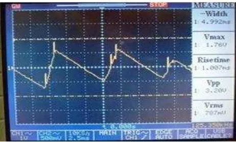
In the simulation result, the output voltage is constant 254 V, it is not decreased. It is assumed that DC boost converter is ideal, so that there is no losses in the component. As the criterion of DC boost converter required by Piotr Biezel that ripple current in the input and output is low [9], so that ripple voltage yielded is 787 mV, and wave defective yielded is very low and ripple current is low. The results ripple voltage of DC boost converter can be obtained in Figure 10.
Figure10 . Ripple Voltage of DC Boost Converter.
4. Conclusion
According to the simulation and test results, the development of inverter as DC boost converter yields voltage of 253 – 254 Vdc. This voltage is still in the limit of operating voltage requirement of equipment, there are minimum of 141 Vdc and maximum of 340 Vdc. From the voltage test of ripple is 787mV, so that the use of inverter as DC boost converter can be applied as DC converter. The result of the development and the experiment show that inverter as DC boost converter will make easy to use renewable energy sources in the future.
Acknowledgments
This work is part of Microgrid System (MS) Research Group Project, Department of Electrical Engineering, University Indonesia.
References
[1] Lasseter, Robert H, Paigi, Paolo. Microgrid: A Conceptual Solution. Power Electronics Specialists
Conference (PESC 04) IEEE 35th Annual. German. 2004; 6: 4285-4290.
[2] Mohammad E. Khodayar, Masoud Barati, Mohammad Shahidehpour. Integration of High Reliability
[3] Manual book SI 5048 U-11, SMA Technologie AG Germany. AC Power Supply Produc for Rural Electrification. 2007: 16-17.
[4] Sun Xiao, Yim-Shu Lee, De-hong Xu. Modeling, Analysis, and Implementation of Parallel
Multi-Inverter Systems With Instantaneous Average – Current – Sharing Scheme. IEEE Transaction on
Power Electronics. 2003; 18(3): 844-856.
[5] Juan C Vasquez, Josep M Guerrero, Alvaro Luna, Pedro Rodríguez, Remus Teodorescu. Adaptive
Droop Control Applied to Voltage-Source Inverters Operating in Grid-Connected and Islanded
Modes.IEEE Transactions on Industrial Electronic. 2009; 56(10): 4088-4096.
[6] Nilsson Daniel, Ambra Sannino. Efficiency analysis of low and medium voltage dc distribution system.
IEEE Power Engineering Society General Meeting. Denver. 2004; 2: 2315-1321.
[7] Youichi Ito, Yang Zhongqing, Hirofumi Akagi. DC Micro-grid Based Distribution Power Generation
System. Power Electronics and Motion Control Conference (IPEMC) The 4th International IEEEl.
2004; 3: 1740 – 1745.
[8] Dylan Dah-Chun Lu, Vassilios G. Agelidis. Photovoltaic -Battery-Powered DC Bus System for Common
Portable Electronic Device. IEEE Transaction On Power Electronic. 2009; 24(3): 849-855.
[9] Piotr Biczel, Lukas Michalski. Simuling Model of Power Electronic Converters for DC Microgrid
Simulation. Power Quality Alternative Energy and Distributed System, in Compatible and Power
Electronic (CPE2009) International Conference – Workshop IEEE. 2009; 6: 161-165.
[10] Fang Lin Luo, Hong Ye. Advanced DC/DC converters. CRC Press. ISBN 0-8493-1956-0. 2004: 20-22.
[11] Piotr Biczel. Power Electronic Converters in DC Microgrid. International Conference – Workshop
(CPE) IEEE. 2007: 1-6.
[12] Hanh-Phuc Le, Seth R Sanders, Elad Alon. Design Techniques for Fully Integrated
Switched-Capacitor DC-DC Converters. IEEE Journal Of Solid-State Circuit. 2011; 46(9): 2120-2131.
[13] Yi-Ping Hsieh, Jiann-Fuh Chen, Tsorng-Juu Liang, Lung-Sheng Yang. A Novel High Step-Up DC-DC
Converter for Microgrid.IEEE Transaction on Power Electronic. 2011; 26(4): 1127-1136.
[14] Felinto SF Silva, Antônio AA Freitas, Sérgio Daher, Saulo C. Ximenes, Sarah K. A. Sousa.High Gain
DC-DC Boost Convertr With A Coupling Inductor. Power Electronics Conference (COBEP '09). 2009: 486-492.
[15] Hongfei Wu, Kai Sun, Runruo Chen, Haibing Hu, Yan Xing. Full-Bridge Three-Port Converters With
Wide Input Voltage Range for Renewable Power Systems.IEEE Transactions on Power Electronics.
2012; 27(9): 3965 – 3974
[16] Ned Mohan, Tore M Undelan, William P Robbins. Power Electronics, Converter, Application and Design. Third Edition. West Susse: John Willey & Sons. 2003: 172-174.
[17] Budiyanto, Rudy Setiabudy, Eko Adhi Setiawan, Uno Bintang Sudibyo. Development Of Direct
Current Microgrid Control For Ensuring Power Supply From Renewable Energy Sources.
![Figure 2. DC Microgrid Diagram [9]](https://thumb-ap.123doks.com/thumbv2/123dok/247207.503825/2.595.128.469.88.317/figure-dc-microgrid-diagram.webp)