F
UNDAMENTALS
TUDY OFI
NTERNALC
RACKM
EASUREMENTONC
ONCRETES
TRUCTURESBYU
SINGS
TICKS
CANNERK
AJIANF
UNDAMENTALP
ENGUKURANI
NTERNALC
RACKP
ADAS
TRUKTURB
ETOND
ENGANM
ENGGUNAKANS
TICKS
CANNERAchfas Zacoeb
Lecturer, Civil Engineering Department – Brawijaya University, Indonesia Jl. MT. Haryono 167 Malang 65145, Indonesia.
E-mail: [email protected]
ABSTRACT
Demand for the development of non destructive test (NDT) techniques have improved with the growing concern about the deteriorating condition of concrete structures. Efficient and accurate imaging techniques are needed for a reliable evaluation of safety and serviceability of concrete structures. Although, presently, imaging is routinely used in various fields, imple-mentation of these technologies in NDT of civil engineering systems, especially of concrete structures, offers many cha-llenges and requires additional development due to the composite nature of the concrete material and the complexities of rein-forced concrete systems. In this paper, the feasibility of visual observation device that developed with small inspection bore-hole for investigating internal crack in concrete structure by scanning technique is presented. Special considerations regarding the applicability and accuracy of these techniques for the condition assessment of concrete structures are discussed, and examples of scanning image are given.
Keywords: internal crack, scanning image, visual observation, small-scale destruction, plural information
ABSTRAK
Tuntutan pengembangan teknik pengujian non destructive test (NDT) meningkat dengan berkembangnya kekhawatiran tentang memburuknya kondisi struktur beton. Efisiensi dan keakuratan teknik pencitraan diperlukan untuk evaluasi yang handal dari keselamatan dan kemampuan layan struktur beton. Meskipun, saat ini, pencitraan secara rutin dimanfaatkan di-berbagai bidang, penggunaan teknologi NDT dalam system teknik sipil khususnya pada struktur beton, menawarkan banyak tantangan dan memerlukan pengembangan tambahan karena sifat komposit dari bahan beton dan kompleksitas dari system beton bertulang. Tulisan ini menyajikan kelayakan bagian pengamatan visual yang dikembangkan dengan pengamatan lubang bor kecil untuk menyelidiki retak di dalam struktur beton dengan teknik scanning. Pertimbangan khusus mengenai penerapan dan akurasi pada teknik ini untuk penilaian kondisi struktur beton diskusikan, dan contoh gambar scanning diberikan.
Kata-kata Kunci: retak internal, gambar scanning, pengamatan visual, kerusakan skala kecil, informasi umum
INTRODUCTION
Concrete is a composite material consisting of a binding medium with particles like gravel, sand etc. embedded in the con-struction medium. Critical concrete structures need to be eva-luated during their service to ensure that they have not deterio-rated and are free from defects. Referring to the practice of the 20th century and analyzing the modern tendencies it is possible to say with reasonable confidence that the reinforced concrete was, still is and will be one of the basic construction materials (Grosse, et al., 2006). This material is used to construct buildings, bridges, tunnels, nuclear reactors and other structure, its exten-sive use requires development of corresponding diagnostics me-thods and means. So it is necessary to build instruments and de-velop procedures providing estimation of a structures condition and to determine its remaining service life.
In Japan, there is an indication that structure maintenance for 50 years old construction is rapidly increasing in the last de-cade. For that reason, an assessment condition of structure mem-ber becomes an important aspect to determine a repair plan of aged structural system and establish the durability. The purpose of inspection is to grasp the performance of a structure and col-lect information necessary for carrying out maintenance. Inspec-tion shall be carried out by suitable methods to discover deterio-ration, damage, or initial defects and to maintain the performance
of the structure above the required level. In the cases when any defect or damage is found, immediate measures shall be taken (JSCE, 2001).
Maintenance and repair strategy should be developed effec-tively that fulfilled with the requirements of deterioration mecha-nism management. This management is conducted by collecting deterioration degree from each individual member into database, and performing initial inspection that normally with simple me-thods, such as hammer tapping and visual observation that cover-ed the visual information data such as cracking, scaling, color change or stain, spalling, exposure, corrosion and rupture of steel reinforcement in concrete (Uomoto, 2003). Another method for assisting the inspection like core drilled will gather an existing concrete condition, and investigate the internal defects, such as carbonation depth, chloride ion diffusion, cracking, void, and corrosion. By this method, relatively big device is required and became difficult to determine the number of inspection mark re-lated with cost and work problems. In addition, there is a partial damage or danger to cut off a steel reinforcing bar in core drilling process.
inspection technology that developed by using a stick scanner to capture concrete surface image from inspection borehole, where-as the where-assessment is confirmed by imaging analysis in photograph stage.
OUTLINE OF STICK SCANNER
The stick scanner that developed for capturing internal con-crete surface image from small inspection borehole is shown in
Figure 1 and the specification of device is shown in Table 1. The internal surface image is captured by inserting the stick scanner aperture mouth into inspection borehole and rotating in clockwise manual movement with one hand to capture all internal surface of inspection hole. The stick scanner is connected to a tablet PC through an USB port.
Figure 1. The stick scanner
Table 1. Specification of stick scanner
Main Body
: 350mm (extent up to 1000mm by installing the extension of steel pipe)
: 1040gr (tablet PC excluded)
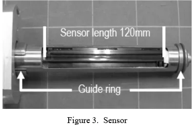
Sensor
: Contact Image Sensor (CIS) : 120mm
The structure of encoder is shown in Figure 2 that consist of three major parts, such as encoder roller, circuit board and stainless steel pipe for inserting the sensor. The encoder is cover-ed by steel box to protect the contents from dust, shake, and damage.
Figure 3. Sensor
Figure 4. Supporter grip
Although hand partial or supporter grip as shown in Figure 4 is a little hard to grab, it has a smooth configuration which cur-ved so that a system could be supported enough on the examina-tion object.
Figure 5. Rotation knob
Rotation knob part as shown in Figure 5 has a ruler and degree of rotation guide for confirming the insertion length and rotation direction of sensor. A rotation of sensor is manual and internal surface image capturing process can be conducted by pressing the start switch to run the scanner software that installed in tablet PC.
Figure 6. Connector cable and steel box
Cable part as shown in Figure 6 is using a curl code with USB port for connecting with tablet PC. By using this cable type, it is possible to conduct a scanning process continuously and a-void a problem from cutting by twist. Steel box is protecting and covering the encoder part from any damage.
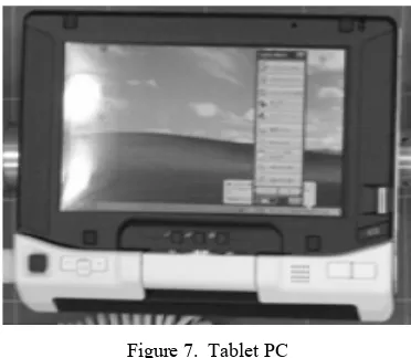
Figure 7. Tablet PC
Tablet PC that used in this experiment is FMV series as shown in Figure 7 with the weight of 580gr. For touch sensitive-ness, a tablet PC can be performed. When image capturing is processed, the scanning image can be displayed and analyzed by touching a monitor. This display monitor size is 5.5” and can be rotated in the arbitrary directions.
LABORATORY WORKS
Calibration of Image Size
The accuracy of image reading representation is investiga-ted by inserting a 1mm grid sheet as shown in Figure 8 into the aluminum stiff pipe of the same internal diameter as an inspect-tion hole. The grid sheet right face is scanned with stick scanner, and a representation image is acquired as shown in Figure 9. The distance of each point of a rotation and axial direction was con-firmed from the representation image, whereas the accuracy was compared with an actual measurement. In addition, with the sensor resolution of 600dpi, the grid sheet length was computed (actual measurement) per mm as 1 pixel is 0.042 mm.
Figure 8. Grid sheet paper
Verification of Crack Width
Figure 9. Representation of captured image
Figure 10. Cylindrical specimens
Figure 11. Artificial crack making
Figure 12. Cracking part image
Characteristic of Image
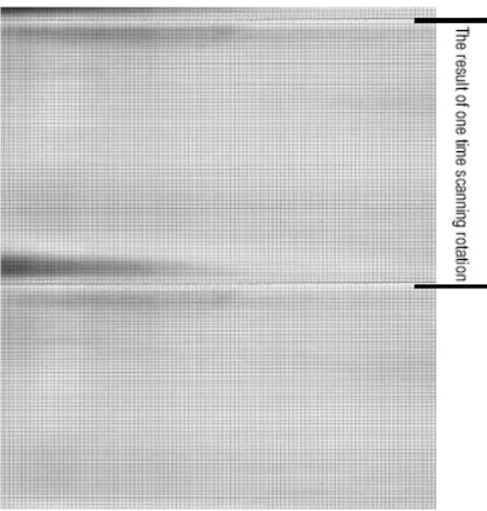
From the acquisition image for one scanning rotation as shown in Figure 13, the result of measurement of the direction of insertion and rotation is shown in Table 2. From this table, the error measurement for insertion and rotation direction became 0.14 and 1.42%, respectively. This error is possible caused by the different of drill diameter between the rings made to rotate the roller of an encoder with the inspection hole, but this error does not pose any problem practically and still in the tolerance level.
Figure 13. The acquisition image
Table 2. Image size measurement error
Direction Pixel Number
Actual (mm)
Experimental (mm)
Error (%)
Insertion 2432 102 102.1 0.14
Rotation 1787 74 75.1 1.42
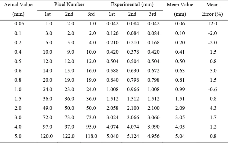
Table 3. Crack width measurement error
Actual Value
(mm)
Pixel Number Experimental (mm) Mean Value
(mm)
Figure 14. Actual crack width VS Experimental
The gap between object and the contact image sensor in this scanner is consistent in two dimensional (insertion and rota-tion direcrota-tion). It means an image pixel always becomes the sa-me size with scanner reading resolution. Scale calibration be-came unnecessary with this scanner, and the distance between two arbitrary points in image can be easily measured from the pi-xels number. The captured image from inspection borehole in maximum reading size of 105 x 356mm for one time scanning is contains more than 20Megapixels that can be obtained at maxi-mum quality of 600dpi. This image is enabled to confirm fine aggregate or cracking condition bigger than 0.1mm.
This scanner can perform accumulation display of image as well as pixel size being constant precisely because there is no image distortion. If the insertion length is more than maximum reading size of sensor, it will require for extra image capturing process by inserted the sensor part deeper into inspection bore-hole. The common parts of image are shown in Fig. 15 and both
images are partially overlapping became one image on PC with composition method.
Figure 15. Composition method of image
INSPECTION PROCEDURE
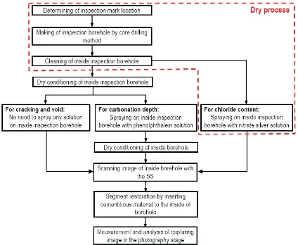
The measurement, such as crack width or carbonation depth that appeared in scanning image is confirmed easily by counting the number of pixels. This digital image characteristic is also enabled to conduct a various analyses. For scanning
ima-ge sample result is shown in Figure 17 that contains information about internal concrete defects, such as carbonation depth, crack condition and alkali silica gel.
Figure 16. Flow chart of various investigations
Figure 17. Sample of final image analysis
CONCLUSION
Internal inspection of concrete structure that conducted by this stick scanner is effective to obtain plural information from one inspection mark. By using a small inspection borehole dia-meter of 24.5mm, it will faster for concrete segment restoration and no giving any significant effect towards structure perfor-mance. The capturing image with maximum quality more than 20Megapixels is enabling for analysis the condition of internal concrete that will be beneficial for assessing and determining the maintenance plan. Future research work will examine the appli-cability of this scanner for field investigation in other internal concrete structures deterioration.
ACKNOWLEDGEMENTS
REFERENCES
Grosse, C.U., dan Kruger, M. (2006). “Inspection and Monitor-ing of Structures in Civil EngineerMonitor-ing.” The e-Journal of Nondestructive Testing, January-2006, Vol. 11 No.1. Japan Society of Civil Engineers (JSCE). (2001). Standard
Spe-cifications for Concrete Structures “Maintenance”. JSCE Guidelines for Concrete No. 4, 2001.
Uomoto, T. (2003). “Utilization of NDI to Inspect Internal De-fects in Reinforced Concrete Structures.” Proceeding in
International Symposium of Non Destructive Testing in Civil Engineering, September 16-19, 2003 in Berlin, Germany. Zacoeb, A., Ishibashi, K., Ito, Y., Miyamoto, N., and Sogabe, M.