“ I hereby declare that I have read through this report entitle “Simulation And Experiment Development For 3-Phase Voltage Dip Mitigation Using D-Q Controller” and found that it has comply the partial fulfillment for awarding the degree of Bachelor of Electrical Engineering (Control, Instrumentation and Automation)”
Signature : ...
Supervisor’s Name : ...
2
SIMULATION AND EXPERIMENT DEVELOPMENT FOR 3-PHASE VOLTAGE DIP MITIGATION USING D-Q CONTROLLER
AHMAD ARIF BIN AHMAD FAUZI
This Report is Submitted in Partial Fulfillment of Requirements for the Degree of Bachelor in Electrical Engineering (Control, Instrumentation and Automation)
Faculty of Electrical Engineering
UNIVERSITI TEKNIKAL MALAYSIA MELAKA
ii
Ahmad ‘Arif Bin Ahmad Fauzi
23 June 2015
I declare that this report entitle “Simulation And Experiment Development For 3-Phase Voltage Dip Mitigation Using D-Q Controller” is the result of my own research except as cited in the references. The report has not been accepted for any degree and is not concurrently submitted in candidature of any other degree.
Signature : ...
Name : ...
iii
iv
ACKNOWLEDGEMENT
I would like to express my deepest appreciation to all those who provided me the possibility to complete this report. A special gratitude to my supervisor Encik Mohamed Azmi bin Said, whose contribution in stimulating suggestions and encouragement, helped me to coordinate my project.
Furthermore, I would like to acknowledge to the FKE’s staff who gave the permission to use all required components to complete the project “Simulation and Experiment Development for 3-Phase Voltage Dip Mitigation using D-Q Controller”.
v
ABSTRACT
vi
ABSTRAK
vii
TABLE OF CONTENTS
CHAPTER TITLE PAGE
DECLARATION ii
DEDICATION iii
ACKNOWLEDGEMENT iv
ABSTRACT v
ABSTRAK vi
TABLE OF CONTENTS vii
LIST OF FIGURES ix
LIST OF TABLES xi
LIST OF APPENDICES xii
1 INTRODUCTION 1
1.1 Motivation 1
1.2 Problem Statement 1
1.3 Objectives 2
1.4 Scope of Research 2
2 LITERATURE REVIEW 4
2.1 Voltage Dip 4
2.2 Voltage Dip Mitigation 5
2.2.1 PI Controller 7
2.2.2 Inverse Park’s And Clark’s Transformation 8 2.2.3 Shunt-Connected Voltage Source Converter (VSC)
11
2.2.4 Phase-Locked Loop 12
2.2.5 SVPWM 12
viii
3 METHODOLOGY 14
3.1 Voltage Dip Mitigation 14
3.2 Full process D-Q controller 17
3.3 Method of Mitigating Power Line Voltage Dip by Current and Voltage DQ Controller
18
3.4 Simulation of Voltage Dip Mitigation 19
3.4.1 Simulation with Voltage Dip 20
3.4.2 Simulation with Voltage Dip 26
3.4.3 Simulation Voltage Dip Using Inverter 28
3.5 RLC Filter 30
4 RESULTS AND DISCUSSION 31
4.1 Simulation Results 31
4.1.1 Process Timeline 32
4.1.1.1 Generator On 33
4.1.1.2 Pi Controller On 36
4.1.1.3 Reactive Current Injected 36
4.1.1.4 Voltage Dip Happened 37
4.1.1.5 Voltage Dip Mitigated 38
4.2 Results Analysis 40
4.2.1 Comparison 40
4.2.2 Transient Analysis 42
5 CONCLUSION AND RECOMMENDATION 44
5.1 Conclusion 44
5.2 Recommendation 45
REFERENCES 46
ix
LIST OF FIGURE
FIGURE TITLE PAGE
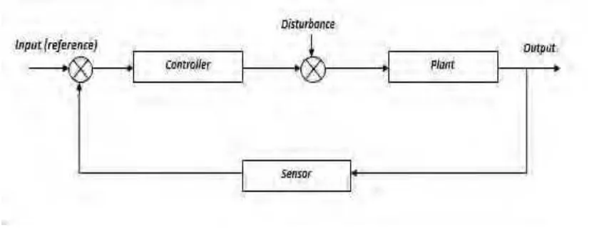
2.1 Basic closed loop control system 4
2.2 Voltage dip waveform 5
2.3 Voltage dip mitigation method 6
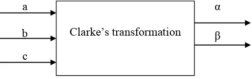
2.4 Block diagram of Clarke’s transformation and Park’s transformation
8
2.5 Clarke’s transformation 8
2.6 Park’s transformation 9
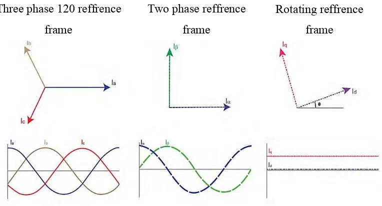
2.7 Graph and polar form of three phase reference frames signal, two phase reference signal and rotating reference frame signal
11
2.8 Block diagram of the implemented control system 12 3.1 Flowchart of mitigating voltage dips process 15-16
3.2 DQ Controller Block Diagram 17
3.3 Sinusoidal waveform of three phase signals 19
3.4 Current and voltage rotating reference frame signal 19
3.5 A system without voltage dip 20
3.6 Vo block 20
37 V block 21
3.8 Vβ block 21
3.9 Vd block 22
3.10 Vq block 22
3.11 PLL block 22
3.12 PI controller 23
3.13 Vα block 24
3.14 Vβ block 24
3.15 Va block 25
3.16 Vb block 25
3.17 Vc block 25
3.18 Simulation with voltage dip 26
x
3.20 Reactive current injected using inverter 29
3.21 Process filter 30
3.22 Filter of RL and RLC circuit 30
3.23 Experimental setup diagram 31
4.1 Process timeline diagram 33
4.2 Line voltage of three phase component 33
4.3 Line voltage of DQ component 34
4.4 Error voltage without and with PI controller 35
4.5 Line voltage when PI controller is activated before signal is stable 35 4.6 Line voltage when PI controller is activated after signal is stable 36
4.7 The generator is start to stable at 0.032s 36
4.8 Reactive current injected into the system 37
4.9 Line voltage in three phase component with voltage dip 38 4.10 Line voltage in DQ component with voltage dip 38 4.11 Line voltage in three phase form after compensation 39
4.12 Line voltage phase A after compensation 40
4.13 Line voltage in DQ form after compensation 41
4.14 Line voltage in three phase component with voltage dip 42 4.15 Line voltage in three phase form after compensation 42
4.16 Line voltage in D form after compensation 44
xi
LIST OF TABLES
TABLE TITLE PAGE
4.1 Settling time of line voltage 32
4.2 Comparison between error voltage without and with PI controller 36 4.3 The comparison for the line voltage while voltage dip and after
compensated
40
4.4 Comparison of line voltage value in three phase 41 4.5 Information gathered from the DQ component graph after
compensation
xii
LIST OF APPENDICES
TABLE TITLE PAGE
A-1 Vα ( transformation ) 48
A-2 Vβ ( transformation ) 48
A-3 Reactive current ( without RLC filter ) 49
A-4 Reactive current ( with RLC filter ) 49
A-5 SVPWM ( Triangle VS Sine wave ) 50
1
CHAPTER 1
INTRODUCTION
1.1 Motivation
Large consumption of electrical power such as in industries are concern about the power quality problems. Generally, the common power quality problems that occurs are voltage swell, interruptions, and voltage dip. The most frequent disturbance that occured is voltage dip and it is considered as the most serious problem compared to other power quality problems. Voltage dip or also known as voltage dip is a short reduction of voltage in a period of time. In order to overcome the problem, most of the high technology industries prefer to implement advanced technology system including the sensitive equipments to apply energy saving concept. However, not all of the sensitive equipments can withstand sudden fluctuation such as voltage dip phenomenon. Thus, the equipments will be malfunction as the voltage dip occurred and resulted to a significant financial losses. The implications of damage to equipments can cause the production process had to terminated. As the example, USA experienced losses over $20 annually due to voltage dip problem. Therefore, it is important to find the solution to mitigate voltage dip problem to increase the productivity, economy and quality in industrial sector.
1.2 Problem Statement
2
the reduction of voltage. In this situation, the reduction of voltage is classified as voltage dip.
An ideal power distribution system should ensure that the customers were provided with uninterrupted flow of energy at smooth sinusoidal voltage at the fluctuation of magnitude and frequency. On the other hand, various linear signals which affect the quality of power supply in power system are significant in real life. Therefore, there are quite impossible to avoid the trigger of the voltage dip and it is important to overcome the problem. Thus, power system analysis is required in order to maintain the voltage level.
1.3 Objectives
The objectives of the project is to:
1. Design a method of mitigating power line voltage dip using current and voltage DQ components by tranforming three phase reference frames to rotating reference frames.
2. Simulate the voltage dip mitigation system by using PSCAD software.
3. Analyze the performance of the uncompensated and compensated system by using simulation software (PSCAD, MATLAB, etc).
1.4 Scope of Research
Power quality problems can be defined as the deviation of current or voltage from the ideal waveform. There are many type of problems such as voltage swells, harmonics, flickers, voltage dips, interruptions, transients, waveform distortions, unbalance and frequency deviations. This research conducted are only focusing on voltage dip problem.
3
In this research, DQ transformation method was selected among other method to analyze and simplify three phase system.
One of the solution to mitigate voltage dip is by injecting reactive power into transmission line. Among other several methods to inject reactive power into transmission line, controlling shunt current DQ component is proposed. To control shunt current DQ component, current source is used as the custom power devices. This research is conducted to mitigate voltage dip by injecting shunt current source.
Furthermore, this researh also applying SVPWM and inverter in the control system which perhaps could give a better result in comparison with the other method used.
4
CHAPTER 2
LITERATURE REVIEW
2.1 Voltage Dip
High power quality system with 100% reliability is the ability of the electrical system to deliver a clean signal without interruptions [1]. Control system consist of generator, transmission line and distribution line as ilustrated in Figure 2.1. In closed loop control system, the sensor can detect the amount of output signal which is not equal to the desired output signal when the plant experience fault. Then the comparison between the output signal and the reference signal is made using the controller. Next, the controller processed the signal and compensate the signals.
Figure 2.1 : Basic closed loop control system
5
One of the most severe problem that always occur in the distribution system is a reduction of voltage called voltage dip [4]. Therefore, there are quite impossible to avoid the trigger of the voltage dip and it is important to overcome the problem. According to IEEE Std.1159-1995, voltage dip can be defined as the momentarily decrease in the root mean square (RMS) voltage of duration greater than half a cycle and less than one minute with magnitude in the range of 0.1 to 0.9 per unit [5].
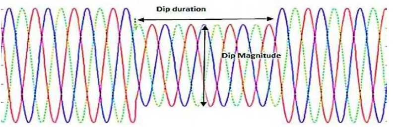
A typical voltage dip example measured in three phase system recorded three sinusoidal waveforms correspond to three phase-to-phase instantaneous voltagesas in Figure 2.2. The voltage show a drop in magnitude and then remain to the same magnitude as at the beginning in the third channel [6].
Figure 2.2 : Voltage dip waveform
2.2 Voltage Dip Mitigation
6
The first action that need to be done in order to improve voltage dip problem in industrial plant is determining which process seems to be sensitive to voltage dip and understands the manufacturing process of the product and the operation of the equipment [7]. There are few different solutions to mitigate the voltage dip problem which are by improving the power system, load immunity and the installation of the mitigation devices [5]. There are few different solutions to mitigate the voltage dip problem which are by improving the power system, load immunity and the installation of the mitigation devices [8]. concluded that among all of the method provided, the installation of the mitigation device seems to be the only methods to protect the system against voltage dip.
Figure 2.3 : Voltage dip mitigation method [8].
The installation of mitigation device such as custom power devices or controllers at suitable location can improve the voltage profile and considerably reduce the power losses since voltage is strongly influenced by random load and fluctuations which is difficult to control [4]. Custom power devices or controllers include converters, injection transformers, static switches, master-control modules, inverters, and energy-storage modules that can perform voltage-regulation functions and current-interruption in a distribution system [9]. In this project, a controller is implemented in order to mitigate voltage dip.
7
is one of the solution available. The most common single phase power conditioning devices in markets are Uninterruptible Power Supply (UPS), Dynamic Compensator (Dynacom), Constant Voltage Transformer (CVT), Dynamic Sag Corrector (DySC), Dip Proofing Inverter and Voltage Dip Compensator (VDC). Otherwise, Dynamic Sag Corrector (MegaDysc), Datawave, Flywheel, Dynamic Sag Corrector (ProDysc), Active Voltage Conditioner (AVC), Dynamic Voltage Restorer (DVR) and three phases Dynamic Compensator (Dynacom) are the power conditioning devices for three phase system
The controller system consist of few elements such as PI controller, inverse Park’s and Clark’s transformation, SVPWM switching technique and inverter. The working principle of the controller system is almost similar to the study from [10]. The shunt active power filter DQ frame mathematical model and control strategy used pulse width modulation (PWM) with PI controller.
2.2.1. PI Controller
Referring to the block plant, the disturbance represent the fault(voltage dip) while the block controller is a feedback controller, such as P controller, PI controller, PD controller or PID controller.
The combination of proportional gain and integral gain is called as PI-controller. The PI-controller can be expressed in the equation that contains proportional gain and integral gain that is abbreviated as Kp and Ki such as in equation (2.1).
u(t) = Kp e(t) + Ki ∫ � dt (2.1)
8
2.2.2. Inverse Park’s And Clark’s Transformation
Three phase reference frame signal can be transformed into rotating reference frame signal by using Clarke’s and Park’s transformation [11]. Clarke’s and Park’s transformation is a mathematical transformation that transform reference frame of three-phase systems into rotating reference frames in order to simplify the analysis of three-phase circuits. However, the Clarke’s and Park’s transformation work in separate way to transform the signals by cascade as sillustrated in Figure 2.4.
Figure 2.4 : Block diagram of Clarke’s transformation and Park’s transformation
Clarke’s transformation is three phase stationary circuit with the parameter of a-b-c system into two phase stationary reference frame such as in Figure 2.3. The variable of two phase stationary reference frame is denoted as α and β.
Figure 2.5: Clarke’s transformation
The three phase stationary parameter from a-b-c system is transformed into two phase stationary reference frame based on the equation (2.2) where F represent the parameter such as voltage, current, line leakage and F is the parameter such as voltage, current, line leakage in abc form.
F = T o . [ F ] (2.2)
9
� o from equation (2.2) is obtained from equation (2.3).
� o=
[
− −
√ −√
]
(2.3)
The equation of two phase stationary reference frame is obtained such as in equation (2.4), (2.5), (2.6), after simplifying equation (2.2),
� = � - (� - �) (2.4)
� = � − �√ (2.5)
� = � +� +� (2.6)
The equation of inverse Clark’s transformation is noted as in equation (2.7), (2.8), (2.9) for each part.
� = � (2.7)
� = − � + √ � (2.8)
� = − � − √ � (2.9)
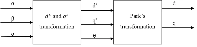
Otherwise, Park’s transformation tranform the three phase stationary parameters into two phase orthogonal rotary reference frame with two variable called d and q (DQ components) as shown in Figure 2.6.
Figure 2.6 : Park’s transformation α β o ds qs θ d � and �
transformation
Park’s
10
The three phase stationary parameters is transformed into two phase orthogonal stationary reference frame based on the equation (2.10) where �� or ��represent the parameter such as voltage, current, line leakage.
� q o (θ) = � q o (θ). [ � o] (2.10)
� q o from equation (2.10) is obtained from equation (2.11).
� q o= [
cαs θ sin θ
− sin θ cαs θ ] (2.11)
Equation (2.12) and (2.13) are involved to transform three phase stationary parameters into two phase orthogonal rotary reference frame.
�� = � cαs � + � sin � (2.12)
�� = −� sin � + � cαs � (2.13)
The equation of inverse Park’s transformation are obtained as in equation (2.14) and (2.15).
� = �� cαs �−��sin � (2.14)
� = ��sin � +�� cαs � (2.15)
11
Figure 2.7 : Graph and polar form of three phase reference frames signal, two phase reference signal and rotating reference frame signal
2.2.3 Shunt-Connected Voltage Source Converter (VSC)
One of the methods to mitigate voltage dip is using shunt-connected VSC [5]. The control system of shunt connected VSC consists of two controllers which are vector current controller and vector voltage controller. The structure of the shunt active power filter is the voltage source inverter (VSI) [10]. The reference signal is generated from vector current controller which is proportional to the VSC output voltage to track the reference VSC output current. While voltage controller generated a reference signal proportional to the output voltage VSC current to maintain the voltage above the capacitor constant to the desired value. The block diagram of the transformation to obtain DQ components of two-phase obtained for three phase system is illustrated in Figure 2.8.
The transformation of three phase system into two-phase system is aimed to simplify the PI controller for sensing the amount of fault in the line voltage. Voltage and current need to be converted to α β then ab need to be converted to obtain DQ components. Morever, the calculation of transformation angle θ(t) is required to calculate DQ components. Then, the transformation angle θ(t) is calculated by Phase-Locked Loop(PLL).
Three phase 120 reffrence frame
Two phase reffrence frame
![Figure 2.3 : Voltage dip mitigation method [8].](https://thumb-ap.123doks.com/thumbv2/123dok/477285.52253/19.595.117.489.287.492/figure-voltage-dip-mitigation-method.webp)