236
ANALYSIS OF DYNAMIC INTERACTION BETWEEN FLEXIBLE BODY
OF OVERHEAD CONTACT WIRE AND ACTIVE CONTROL
PANTOGRAPH CONSIDERING VERTICAL BODY VIBRATION
Mohd Azman Abdullah1,a*, Rustamreen Jenal2,b, Yohei Michitsuji3,c and Masao Nagai4,d
1,2 Universiti Teknikal Malaysia Melaka/Faculty of Engineering, Malacca, Malaysia. a
Email: [email protected], bEmail: [email protected]
3 Ibaraki University/Department of Mechanical Engineering, Ibaraki, Japan. cEmail: [email protected] 4 Tokyo University of Agriculture and Technology/Department of Mechanical Systems Engineering, Tokyo, Japan.
c
Email: [email protected]
Abstract—The current collection system consists of a pantograph placed on the roof top of a trains’ vehicle and overhead contact wire supported by evenly spaced vertical holders which supply the current to the pantograph from the electric power grid. Most of the pantographs produce averagely good performances at low and medium speeds, approximately less than 250 km/h. However, at higher speeds, the response of the pantographs is distorted. Thus the stability of the current collection is in peril. In addition, due to vertical vibration of the car body during high speed, contact force variation occurs between the pantograph and overhead wire. Therefore, it is necessary to maintain the contact between pantograph and overhead wire. In this study, the multi-body dynamics analysis is used to model the flexible body of overhead wire. An excitation experiment is performed in order to determine the parameters of pantograph. With consideration of vertical body vibration, an active pantograph control is developed to eliminate the effect of vibration to contact force, reduce the maximum peaks and avoid contact loss.
KeywordsüMulti-body Dynamic Analysis; Active Pantograph;
Interaction; Active Control.
I. INTRODUCTION
In recent years, high speed railway vehicle technologies have been studied and investigated in order to develop their performances with the objectives of improving riding comfort, reducing noise and increasing efficiency from an environmental perspective. One of the essential performances is current collection stability. Operating at a high speed condition, the current collection system which consists of contact wire and pantograph suffers from contact force variation. In order to understand the contact force variation, a study of the dynamic interaction between contact wire and pantograph is essential.
The current collection system consists of a pantograph placed on the roof top of a trains’ vehicle and overhead contact wire supported by evenly spaced vertical holders which supply the current to the pantograph from the electric power grid. Most of the pantographs produce moderately good performances at low and medium speeds, approximately less than 250 km/h. However, at higher speeds, the response of the pantographs is distorted by the irregularities of the contact wire. Thus, the stability of the current collection is in peril. In addition, due to vibration of the car body and external drag force produced during high speed, contact force variation occurs between the pantograph and overhead
wire. In the field on electromagnetic interference due to the contact variation, the subject has been discussed widely by researchers. The sliding contact of the pantograph and overhead wire results in unwanted radiated fields [1] at the contact area. The electric arcs generated from losing mechanical contact between the pantograph and the overhead wire cause electromagnetic emission [2]. The change of pantograph static parameters in improving the contact also affect the electromagnetic radiation level [3][4]. At speeds of more than 300 km/h, the main problems for the current collection systems are: the increment of the rate of pantograph bounce from the overhead wire; the increment of the wear of the contact slip and overhead wire; and the increment of the noise levels [5].
In order to ensure adequate current supply to the train, it is necessary to modify or control the response of the pantograph. At static conditions, the pantograph should be designed to provide a constant nominal contact force of about 54 N [6] between the contact strip and the overhead contact wire. While in dynamic conditions, the contact force should never drop to zero to prevent contact loss. The variation of the contact force between pantograph and overhead wire is acceptable at a certain range. As long as there is no contact loss and the utmost contact is supportable by the system, the current collection system can perform desirably. This is the aim of the control approaches in the development of active control pantograph. Within the acceptable range, the contact force data perhaps can be utilized for other purposes. The overhead wire unevenness can be measured and estimated using the data [7]. The overhead wire strain and diagnosis are also performable by means of contact force [8][9].
237
vertical body vibration. Within reasonable amplitude, stationary and non-stationary pantograph simulations are performable to analyze the effect of vertical body vibration to the contact force variations. Furthermore, incorporating the vibration in the multi-body dynamics analysis of the contact wire and pantograph interaction will strengthen the approach of the analysis and the attempt to control the force discrepancy.
II. CONTACT WIRE AND PANTOGRAPH MODELING
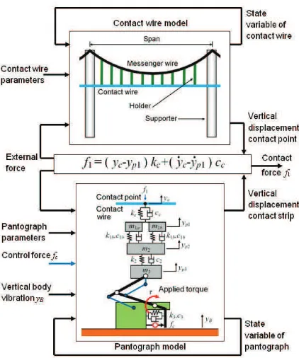
The flexible body modeling approach using multi-body dynamics analysis, absolute nodal coordinate formulation (ANCF) [11][12][13] accompanied with damping force formulation [14][15] is used to model the overhead contact wire (Fig. 1). An asymmetrical z-shape pantograph unit with two contact points was utilized as shown in Fig. 2. The contact wire and pantograph parameters (Table 1 and 2) are taken from the previous published researches [11].
Figure 1. Structure of contact wire system.
Figure 2. Pantograph physical model.
Table 1. Contact wire parameters.
Parameter Symbol Value and unit
Length of span s 50 m
Number of span ns 2
Number of holder nh 10/span
Wire diameter d 15.49x10⁻³
m Young’s modulus E 130x109
Ns/m2
Mass density 8920 kg/m3
Damping parameter D 3.239 x 10⁷
Drag coefficient CD 0.8
Fluid density f 1.2929 kg/m 3
Gravity g 9.8 m/s2
Wire tension T 19600 N
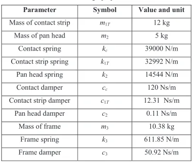
Table 2. Pantograph parameters.
Parameter Symbol Value and unit
Mass of contact strip m1T 12 kg
Mass of pan head m2 5 kg
Contact spring kc 39000 N/m
Contact strip spring k1T 32992 N/m
Pan head spring k2 14544 N/m
Contact damper cc 120 Ns/m
Contact strip damper c1T 12.31 Ns/m
Pan head damper c2 0.11 Ns/m
Mass of frame m3 10.38 kg
Frame spring k3 611.85 N/m
Frame damper c3 50.92 Ns/m
III. CONTACT WIRE AND PANTOGRAPH ANALYSIS
In order to study the interaction between contact wire and pantograph, one should give attention to the dynamic behaviors of both contact wire and pantograph. It has been observed that at high speed, short-period separations between pantograph and contact wire occur frequently and periodically [16]. The reasons for these separations have been investigated and the dynamic behavior of the current collection system has also been improved.
The pantograph model and contact wire model interact together to generate contact force. The contact force acts on a point on top of the contact strip, with spring and damper models. This contact point moves together with the pantograph. Due to the relative displacement and relative speed of the top and bottom of the wear plate as well as flexible body of contact wire, contact force occurs. If the relative speed is less than zero, then the pantograph is considered in bounce condition and is restrained with the spring and damper. Considering the contact point between pantograph and contact wire, the force equation can be written as,
!
c c p!
cp
c
y
k
y
y
c
y
f
1$
"
1#
"
1 (2) Where f1 is the contact force, yc is the contact point displacement, yp1 is the contact strip displacement, kc andcc are the contact spring stiffness and damping parameter respectively. The effect of vertical body vibration to the contact force is also considered. The analysis o the flow of contact wire and pantograph system is shown in Fig. 3. Traveling speed v for the analysis is set at 100, 150, 200, 250, 300, 350 and 400 km/h. The displacement yc is produced from the multi-body dynamic analysis and yB is the random frequency constant amplitude of vertical body vibration. The output of the system is the contact force f1.
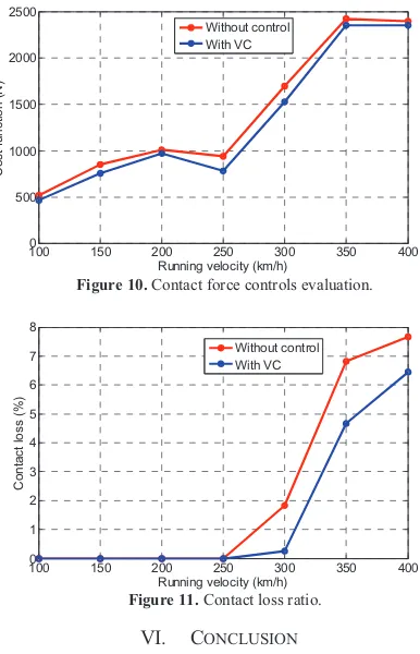
The evaluation of control force is calculated using cost function (CF) with formulation of the sum of area under the graph of contact force about the nominal contact force (f1N) of 54 N.
!
%
&' ( )
* +
" # " , -. / 0 1 2
$ #
d
n
i
N i N
i f f f
f t v
CF 1 1 1 1 1
2 6 . 3
238
Where nd is the number of data sampling, i is the current data, v is the speed (km/h) and 2t is the time interval between data which is equal to 0.02 s.
Figure 3. Contact wire and pantograph interaction system with active
control.
IV. ACTIVE PANTOGRAPH CONTROL
With the intension to minimize the vibration, the vibration cancellation control is applied. Based on transfer function (TF), the controller is designed to produce displacement which is equal but opposite to the one that is produced by the pantograph due to the vertical vibration. The torque ! occurs at the lower frame caused by main spring k3 and damper c3 installed in the
framework which produces the upward force. The damper in the actual design pulls the brake for the framework when the pantograph descends to a certain point. The control force fC is applied to the lower frame,
!
fc lf2$
3
(3)Where lf2 is the length of the lower pantograph frame,
which is equal to 1 m. The pantograph is controlled using vibration cancellation (VC) (Fig. 4). Fig. 5 shows the transfer function block diagram of the controller design with controller K(s), the pantograph G1(s) and actuator
G2(s). The vibration cancellation control force is denoted
as fcVC.
Figure 4. Block diagram for vibration cancellation control.
Figure 5. Block diagram of VC with transfer function.
The equations of motion for the pantograph system are shown in Eqn. (4), (5) and (6).
!
1 1 2!
1 21 1 1
1 y c y y k y y f
mT p # T p " p # T p " p $ (4)
!
2 2 3!
1 1 2!
1 1 2!
3 2 2 2
2yp c yp yp k yp yp cT yp yp kT yp yp
m # " # " $ " # "
(5)
!
c p p p pp cy k y k y y f
y
m3 3# 3 3# 3 3$ 2 2" 3# (6)
The above equations can be simplified using transfer function for block analysis and controller design. By neglecting the f1 and assuming fc = 0, the transfer function
for input yB and output yp1 is,
!
!
!
s
Y
s
Y
s
G
B p1
1
$
(7)The detail transfer function of G1(s) is,
(8)
And, assuming yB = 0, the transfer function for input fc
and output yp1 is,
!
!
!
s
F
s
Y
s
G
C p1
2
$
(9)The detail transfer function of G2(s) is,
(10)
The numerator and denominator constants of G1(s) and
G2(s) are summarized in Table 3. With the intention of
zeroing the total displacement yp1, the controller K(s) is
derived by,
(11)
!
!
!
s
G
s
G
s
K
2 1
239
The detail TF of K(s) is,
(13)
The numerator and denominator constants of controller K(s) are summarized in Table 4.
Table 3. Numerators and denominators for G1(s) and G2(s).
Constant Value Constant Value
N4G1 5.76 x10⁸ N3G2 2.88 x10⁶
N3G1 4.61 x10¹¹ N2G2 1.87 x10⁹
N2G1 1.35 x10¹⁴ N1G2 2.96 x10¹¹
N1G1 1.73 x10¹⁶ N0G2 2.70 x10¹³
N0G1 8.10 x10¹⁷ D7G2 7.34x10⁴
D7G1 7.34x10⁴ D6G2 2.52 x10⁷
D6G1 2.52 x10⁷ D5G2 3.12 x10⁹
D5G1 3.12 x10⁹ D4G2 4.10 x10¹¹
D4G1 4.10 x10¹¹ D3G2 2.01 x10¹³
D3G1 2.01 x10¹³ D2G2 1.44 x10¹⁵
D2G1 1.44 x10¹⁵ D1G2 1.73 x10¹⁶
D1G1 1.73 x10¹⁶ D0G2 8.10 x10¹⁷
D0G1 8.10 x10¹⁷
Table 4. Numerators and denominators for K(s).
Constant Value Constant Value
N11K -4.23 x10¹³ D12K 2.12 x10¹¹
N10K -4.83 x10¹⁶ D11K 6.33 x10¹⁴
N9K -2.34 x10¹⁹ D10K 7.17 x10¹⁰
N8K -6.35 x10²¹ D9K 4.00 x10²⁰
N7K -1.12 x1024 D8K 1.26 x10²³
N6K -1.40 x1026 D7K 2.48 x1025
N5K -1.30 x1028 D6K 3.34 x1027
N4K -8.83 x1029 D5K 3.33 x1029
N3K -4.39 x1031 D4K 2.41 x1031
N2K -1.58 x10² D3K 1.24 x1033
N1K -2.80 x1034 D2K 4.89 x1034
N0K -6.56 x1035 D1K 8.31 x1035
D0K 2.19 x1037
V. RESULTS AND DISCUSSIONS
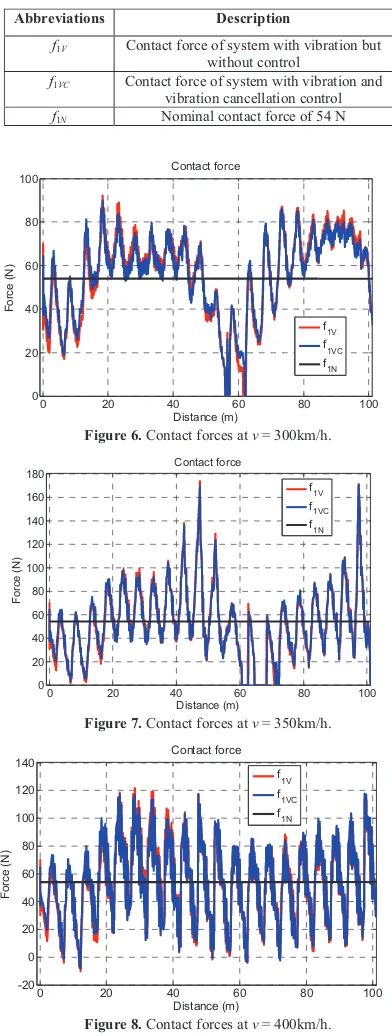
Table 3 summarizes the force abbreviations. Fig. 6 to 8 show the graphical results of the dynamic analysis at speed of 300, 350 and 400 km/h. In the VC control approach, the control force is applied in order to minimize the effect of vertical vibration. The VC control system has consistently reduced the CF and CL for all speeds (Fig. 9 and 10).
Table 3. Contact forces abbreviations.
Abbreviations Description
f1V Contact force of system with vibration but
without control
f1VC Contact force of system with vibration and
vibration cancellation control f1N Nominal contact force of 54 N
0 20 40 60 80 100
0 20 40 60 80 100
F
o
rc
e
(
N
)
Contact force
Distance (m)
f1V f
1VC
f
1N
Figure 6. Contact forces at v = 300km/h.
0 20 40 60 80 100
0 20 40 60 80 100 120 140 160 180
F
o
rc
e
(
N
)
Contact force
Distance (m)
f
1V
f1VC f1N
Figure 7. Contact forces at v = 350km/h.
0 20 40 60 80 100
-20 0 20 40 60 80 100 120 140
F
o
rc
e
(
N
)
Contact force
Distance (m) f
1V
f
1VC
f
1N
240
100 150 200 250 300 350 400
0 500 1000 1500 2000 2500
C
o
s
t
fu
n
c
ti
o
n
(
N
)
Running velocity (km/h) Without control With VC
Figure 10. Contact force controls evaluation.
100 150 200 250 300 350 400
0 1 2 3 4 5 6 7 8
C
o
n
ta
c
t
lo
s
s
(
%
)
Running velocity (km/h) Without control With VC
Figure 11. Contact loss ratio.
VI. CONCLUSION
The practical application of multi-body scheme, ANCF was used to model the interaction between contact wire and pantograph with the consideration of vertical body vibration. The design of active pantograph controls via simulation was also investigated. In an attempt to eliminate contact loss between contact wire and pantograph, the control approaches have been tested at high speeds. The active controls are designed with the application of the multi-body dynamic analysis. The development of the active pantograph control depends on the availability of the active damper with high frequency response to produce such control forces.
ACKNOWLEDGMENT
The author (Mohd Azman Abdullah) would like to acknowledge the financial support from the Ministry of Higher Education of Malaysia and Universiti Teknikal Malaysia Melaka.
REFERENCES
[1] Leva, S., Morando, A. P. and Zich, R. E.: On the Unwanted Radiated Fields due to the Sliding Contacts in a Traction System, IEICE Transactions on Communications, Vol.E83BB, No.3, 519-524 (2000).
[2] Tellini, B., Macucci, M., Giannetti, R. and Antonacci G. A.: Line-Pantograph EMI in Railway Systems, IEEE Instrumentation & Measurement Magazine, Vol.4, No.4, 10-13 (2001).
[3] Zhang, C., Zhao, J. and Huang, J.: The Evaluation of the Electromagnetic Emission from High-speed Railway by Pantograph and Network Parameters, Proc. of the CEEM Asia-Pacific Conference on Environmental Electronics, 279-284 (2000).
[4] Zhang, C. and Huang, J.: Predicting the General Electromagnetic Radiation Level on High Speed Railway by the Static Parameters of Pantographs and Networks, Proc. of the 3rd
International Symposium on Electromagnetic Compatibility, 387-390 (2002).
[5] Oshima, T. and Suzuki, S.: High Performance Pantograph for High Speed EMUs, Proc. of the International Conference on Main Line Railway Electrification, 124-128 (1989).
[6] Aboshi, M. and Manabe, K.: Analyses of Contact Force Fluctuation between Catenary and Pantograph, Quarterly Report of RTRI, Vol.41, No.4, 182-187 (2000).
[7] Nagasaka, S. and Aboshi, M.: Measurement and Estimation of Contact Wire Unevenness, Quarterly Report of RTRI, Vol.45, No.2, 86-91 (2004).
[8] Kusumi, S., Fukutani, T. and Nezu, K.: Diagnosis of Overhead Contact Line based on Contact Force, Quarterly Report of RTRI, Vol.47, No.1, 39-45 (2006).
[9] Aboshi, M., Kusumi S. and Kuraoka, T.: Estimation Method of Contact Wire Strain Based on Contact Force between Pantograph and Catenary (in Japanese), RTRI Report, Vol.24, No.2, 23-28 (2010).
[10] Usuda, T., Aboshi, M. and Ikeda, M.: Study of the Relationship between Vertical Acceleration of Carbody and Pantograph Contact Force (in Japanese), The JSME Jointed Railway Technology Symposium, 271-274 (2000).
[11] Abdullah, M. A., Michitsuji, Y., Nagai, M. and Miyajima, N., Integrated Simulation between Flexible Body of Wire and Active Control Pantograph for Contact Force Variation Control, Journal of Mechanical Systems for Transportation and Logistics, Vol. 3, No. 1, 166-177 (2010).
[12] Shabana, A. A., Hussein, H. A. and Escalona, J. L.: Application of the Absolute Nodal Coordinate Formulation to Large Rotation and Large Deformation Problems, Journal of Mechanical Design, Vol.120, 188-195 (1998).
[13] Seo, J-H., Kim, S-W., Jung, I-H., Park, T-W., Mok, J-Y., Kim, Y-G. and Chai, J-B.: Dynamic Analysis of a Pantograph-Catenary System using Absolute Nodal Coordinates, Vehicle System Dynamic, Vol.44, No.8, 615-630 (2006).
[14] Takahashi, Y. and Shimizu, N.: Study on the Elastic Force for the Deformed Beam by means of the Absolute Nodal Coordinate Multibody Dynamics Formulation, Transactions of the Japan Society of Mechanical Engineers, Series C, Vol.67, No.655, 626-632 (2001).
[15] Abdullah, M. A., Michitsuji, Y., Takehara, S., Nagai, M. and Miyajima, N., Swing-up Control of Mass Body Interlinked Flexible Tether, The Archive of Mechanical Engineering, Vol. LVII, No. 2, 115-131 (2010).