INVESTIGATION OF THE CHARACTERISTICS OF BARIUM STRONTIUM TITANATE (BST) DIELECTRIC RESONATOR CERAMIC LOADED ON ARRAY ANTEN-NAS
F. H. Wee1, *, F. Malek2, S. Sreekantan3, A. U. Al-Amani3,
F. Ghani1, and K. Y. You4
1School of Computer and Communication Engineering, Universiti
Malaysia Perlis (UniMAP), Blok A, Kompleks Pusat Pengajian Seberang Ramai, 02000 Kuala Perlis, Perlis, Malaysia
2School of Electrical Systems Engineering, Universiti Malaysia Perlis
(UniMAP), Blok A, Kompleks Pusat Pengajian Seberang Ramai, 02000 Kuala Perlis, Perlis, Malaysia
3School of Materials and Mineral Resources Engineering, Universiti
Sains Malaysia (USM), Seri Ampangan, 14300, Nibong Tebal, Seberang Jaya Selatan, Pulau Pinang, Malaysia
4Department of Radio Communication Engineering, Faculty of
Engineering, Universiti Teknologi Malaysia, 81310 UTM Skudai, Malaysia
Abstract—We investigated a dielectric resonator ceramic microstrip patch antenna. The antenna was formed using barium strontium titanate (BST), which had a dielectric constant of 15. A new approach, i.e., the use of a high temperature dielectric probe kit, was used to determine the dielectric constant of BST. A computer simulation technology (CST) microwave studio was used to simulate the BST array antennas, taking into consideration the dielectric constant. We also measured the gain of the antennas loaded with two-, four-, and six-element arrays of the BST antenna and found that the gain of a six-element BST array antenna was enhanced by a gain of about 1.6 dB over the four-element BST array antenna at 2.3 GHz. The impedance bandwidths of these BST array antennas for voltage standing wave ratio (VSWR) < 2 were in the application ranges,
Received 8 August 2011, Accepted 16 October 2011, Scheduled 24 October 2011
i.e., 2.30 to 2.50 GHz, established for Worldwide Interoperability for Microwave Access (WiMAX) and Wireless Local Area Network (WLAN). Compared with the conventional array antenna with the same aperture size, the performance of the antenna obviously was improved, and the design is suitable for array applications, including base stations, for example.
1. INTRODUCTION
In recent years, dielectric resonator antennas (DRAs) have become attractive due to their particular advantages for some applications, including zero conductor loss and low profile. It has been shown experimentally that this kind of element can be an efficient radiator [1]. Experimental and theoretical evaluations of DRAs have been reported by many investigators [1–8], although the results presented by these investigators are, for the most part, applicable at high resonant frequencies (7 to 12 GHz).
DRAs have a limited bandwidth of operation due to their resonant nature, but this can be improved by reducing the inherent Q-factor of the resonant antenna. One simple approach for reducing the Q -factor is to decrease the dielectric constant [8]. Although this is a simple solution, there are drawbacks. In particular, the size of the antenna will be increased, and this may not be desirable for many applications. Some other reported bandwidth enhancement techniques have included stacked twin dielectric resonators [3] and the use of multi-layer dielectric materials [8].
Ceramic materials can now be broadly considered to be all inorganic, non-metallic materials. However, it is more useful to classify them as polycrystalline, non-metallic materials [9–13]. The inherent physical properties of ceramics have made them desirable for use in a wide range of industries, and they were first applied in the electronics sector.
Al-Zoubi et al. [1] focused more on describing the field distribution in the dielectric resonator antenna (DRA) with the image line at the narrow slot coupled to the DRA side. The availabilities of exciting modes and electric and magnetic fields were analyzed, and it was verified that Q-factor, resonant frequency, and radiation efficiency of the DRA were in good agreement with the results available in the literature. Hence, this analysis triggered our interest in studying the field of BST dielectric resonator ceramics, and we also used the new, well-known “Marcatili method” as a technique for determining effective dielectric constant and excitation mode matching. This method described a slightly more refined approximation that is restricted to rectangular cross-section waveguides. In other research on DRAs conducted by Ain et al., a cylindrical dielectric resonator antenna (DRA) using barium titanate (BaTiO3) with a high dielectric constant
(εr = 1000) was investigated [2]. The authors conducted their experimental study on different heights of a cylindrical Dielectric Resonator, DR and concluded that different thicknesses of DR gave different resonant frequencies. In addition to thickness, we also considered the dimensions and the number of arrays of BST dielectric resonator ceramic, both of which will affect the performance of the antenna. Thus, in our research, we used dielectric resonator ceramics that had high dielectric constants in the fabrication of miniaturized dielectric resonator antennas, thereby affecting the antennas’ radiation characteristics, such as efficiency, radiation patterns, and bandwidth. Thus, our research provided important parameters, such as return loss, antenna gain and directivity, antenna radiation patterns, and antenna power measurements which provide the desired information concerning the performance of the barium strontium titanate (BST) array antenna in both computer simulation and hardware measurement.
Various DRA shapes have been used in the past, but the rectangular shape was chosen since it exhibited the greatest design flexibility, offering a second degree of freedom. A cylindrical DRA only has one degree of freedom, and a hemispherical DRA offers zero degree of freedom. The design can be either a tall and slender or a thin with a wide aspect ratio, depending on the particular need. In addition, rectangular DRAs also have some advantages over other DRA shapes in that it is easy to shape manually into the desired size. Sand paper can be used for polishing the eight flat surfaces, the mode degeneracy problem can be avoided by choosing the proper dimensions, and the bandwidth can be optimized [15].
elements was determined. The design goal was to achieve antenna return loss of less than −10 dB to accommodate an efficient antenna feed. As will be shown, the final design obtained an impedance bandwidth between 2.30 and 2.50 GHz with high gain and good efficiency. In this study, dielectric resonator ceramic array antennas were designed with a rectangular cross-sectional area, and referred to as rectangular DRAs.
The size of the DRA is proportional to
λ
√ε (1)
whereλis the free space wavelength at the resonant frequency, andεis the dielectric constant of the material. The wavelengthλof a sinusoidal waveform travelling at constant speedv is given by: λ=v/f, wherev
is the phase speed (magnitude of the phase velocity) of the wave, andf
is the frequency of the wave. In the case of electromagnetic radiation, such as light in free space, the phase speed is the speed of light, about 3×10⁸ms−1.
2. BST FABRICATION
(Ba1−xSrx)TiO3 solid solution (BST), with different molar composi-tions (x= 0.5) was prepared from raw materials by conventional solid-state reaction, and its structural parameters, crystallite sizes, and bulk densities were determined.
2.1. Preparation of Bulk BST
The BST was initially prepared from commercial BST powder (Pfaltz & Bauer, 99%) with fine particle sizes below 100 nm. The BST powder was compacted uniaxially at a pressure of 75 MPa into a rectangular shape with dimensions of 25 mm × 5 mm. The green bodies were sintered at 1300◦C for three hours in an electric furnace (Carbolite, CWF 1400) for the purpose of densification. Sintering of this material at the indicated temperature had been reported elsewhere [15]. The sintered bodies were polished gently with SiC paper to obtain the following dimensions: 8 mm×3 mm, 4.5 mm×3 mm, and 2 mm×2.5 mm. The raw BST was ground to obtain pellets of the desired size.
2.2. Bulk BST Characterization
microscopy (FE-SEM). The phase formation was analyzed using X-ray diffraction (XRD) for different 2θ angles from 10◦ to 90◦ (Bruker). The Rietveld refinement was performed with the Rietveld program package, X’pert HighScore Pluss. The structural parameters, such as lattice constant, volume, density, crystallite size, and strain, were determined using the Rietveld refinement. The relative density was measured according to the Archimedes concept. Both surfaces of the BST were coated with silver conductive paint to enhance the ohmic contact. The dielectric properties of the ceramic were measured at room temperature for low frequencies from 100 to 1,000,000 Hz using a LCR meter (Inductance (L), Capacitance (C), Resistance (R)) (Agilent 4285), however, the microwave investigations using Agilent 85070B High Temperature Dielectric Probe at room temperature indicated that the dielectric constant was about 15 and that losses smaller than 1% occurred in the frequency range from 2 to 3 GHz. Thus, the results indicated that some BST dielectric ceramics have a paraelectric phase that is suitable for microwave devices and applications.
3. ANALYSIS OF BULK BST
3.1. Field Emission SEM Study
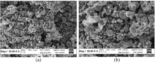
Figure 1 shows the micrographs of BST commercial powder taken by Field Emission SEM at different magnifications. According to the micrographs, the observed particles are mainly smooth and spherical with diameters ranging from 25 nm to 265 nm.
The average particle size was 88.6 nm. The small and large particles can be observed clearly in the micrographs. It was reported that small particles were formed from one droplet, while the larger
(a) (b)
(a) (b)
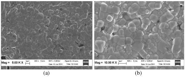
Figure 2. Field Emission SEM of BST after sintering at 1300◦C for three hours.
particles were formed from two or more droplets via the fusion effect [17]. Similar observations were made in examining commercial BST powder. Additionally, the observed powder also exhibited less agglomeration as compared to sol-gel derived powders of BST which is very significant for densification process. Evidently, the densification has a strong dependency on homogeneous microstructures with a narrow distribution of grain sizes [18].
Figure 2 is the microstructure of the BST ceramic derived from sintering at 1300◦C with three hours of soaking time. Typically, the final grain size of the ceramic depends significantly on the sizes of the initial particles. As measured, the average grain size obtained was 0.86µm. The observed microstructure was relatively uniform
with a minimal quantity of small pores at the grain boundary. The number of pores was reduced due to the densification process with a relative density of about 98%. The microstructures that have uniform grain size and high relative density are expected to have a higher dielectric constant, which has been tested for utilization in microwave applications. This also was reported in several publications [19].
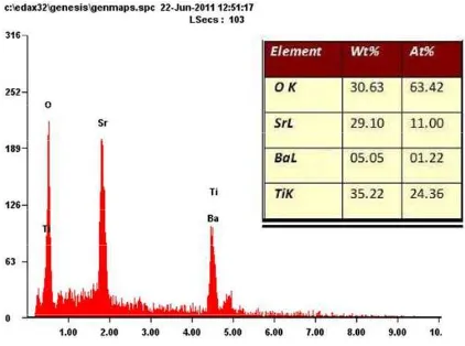
3.2. Energy Dispersive X-ray (EDX) Analysis
Figure 3. Energy dispersive X-ray (EDX) spectra of BST sintered at 1300◦C for three hours.
3.3. XRD and Rietveld Refinement Study
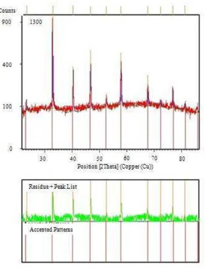
The X-ray diffraction (XRD) pattern of the sintered BST is shown in Figure 4. All the reflection peaks of the observed ceramic were identified and indexed using the XRD data compiled in the standard Power Diffraction File (PDF) data (01-089-8211). As shown in this figure, the observed ceramic consisted of a single phase of layered perovskite BST with a free secondary phase. This result suggested that the pure phase was stable at higher sintering temperatures. Additionally, the pattern fit well with cubic phase BST.
Another observation was that the cubic phase no longer existed at the (200) peak in the XRD pattern after the peak split. It was reported that the peak splits at (002) and (200) indicated the presence of the tetragonal phase, whereas the patterns are characteristic of a cubic phase when (002) was diminished [20].
Figure 4. X-ray diffraction (XRD) pattern of the sintered BST at 1300◦C for 3 hours.
3.4. Dielectric Properties
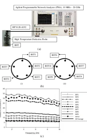
Dielectric constant is the ratio of the electrical conductivity of a dielectric material to the electrical conductivity of free space. Given its definition, the dielectric constant of a vacuum is 1. Any material is able to polarize more than a vacuum, so the k of a material is always > 1. In our research, we investigated the new aspect of the development and utilization of the Agilent 85070B High Temperature Dielectric Probe Kit in measuring the dielectric constant of the dielectric resonator ceramic material, whereas most researchers have utilized an LCR meter or an Impedance Analyzer. With the use of a dielectric probe, measurements can be conducted up to 50 GHz, while the LCR and Impedance Analyzer techniques only can reach a maximum frequency of about 1 MHz. Thus, the Agilent 85070B High Temperature Dielectric Probe Kit was used to measure the intrinsic electrical properties of BST in the frequency bands of 1 to 10 GHz. To measure the dielectric constant of BST, the measurement system included an Agilent 85070B High Temperature Dielectric Probe, an Agilent Microwave Network Analyzer, and Agilent 85070 software. This measurement system made dielectric measurements quickly and easily with no special fixtures or containers required. To measure the dielectric constant of BST, a single flat surface of cylindrical BST was pressed by the dielectric probe, as shown in Figure 6(a). The probe then transmitted a signal into the material under test (MUT), i.e., the BST. The measured reflected response from the BST material was related to its dielectric properties via Agilent 85070 software.
As shown in Figure 6(b), the experiment was conducted with 10 different points for the dielectric constant measurement to ensure the accuracy of the measurements. Both top and bottom parts of the cylindrical BST were measured at five points, respectively. However, the middle part of the cylindrical BST was not considered in the measurement due to the high possibility of obtaining inaccurate results because of the air gap that occurred between the dielectric probe and the BST material.
BST
High Temperature Dielectric Probe
Agilent Programmable Network Analyzer (PNA), 10 MHz – 20 GHz
HP 8120-6192
BST1 BST6
BST2
BST3 BST4
BST5 BST7
BST8 BST9
BST10
(i) (ii)
(c) (a)
(b)
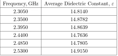
Table 1. Average dielectric constant,ε, of BST at selected frequencies in the range of 2.3 to 2.5 GHz.
Frequency, GHz Average Dielectric Constant, ε
2.3050 14.8140
2.3500 14.8782
2.3950 14.8639
2.4400 14.7636
2.4850 14.7805
2.5300 14.9150
locations were different for the same frequency ranges. This is due to the presence of different stress concentration of substances at the cylindrical edges or points where the field distribution is higher or lower than the average. The concentration is probably depended on the uniform placement of a microstructure throughout the material. Thus, various BST dielectric constant values likely occurred because the microstructure of the BST powder is not evenly distributed over the entire surface of the cylindrical BST. This resulted from the period and temperature that were selected for sintering the BST powder.
In addition, another challenge in BST ceramic is to maintain a repeatability of the dielectric constant. This is because the dielectric constant of ceramic also is dependent to a significant extent on grain size. It was reported that the dielectric constant increased as the initial grain size of the final ceramic increased [20]. In the present study, the variation in the values of the dielectric constant at different spots was attributed to differences in the grain size, as shown in the field emission scanning electron microscopy (FESEM) micrographs in Figures 1 and 2. Thus, in order to overcome the different values of dielectric constants, the practical measurement at different spots of the BST is necessary. The average value for the dielectric constant of the BST dielectric resonators is shown in Figure 6(c).
4. ANTENNA DESIGN
A dielectric ceramic that is not enclosed entirely by a conductive boundary can radiate as an antenna [21–30]. This was the first part of this investigation, which was conducted to determine the effectiveness of ceramic dielectric as a radiating element. The choice of the dielectric ceramic material plays a significant part in the design of the DRA. Due to various research findings, a dielectric ceramic was chosen for use in the design of the DRA [25].
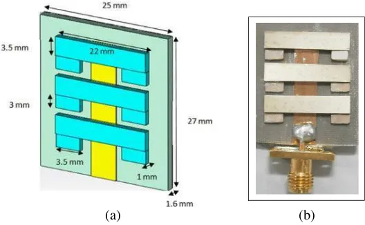
In the proposed design, two, four and six rectangular DRAs, each with the same height h, width w, and thickness t, respectively were arranged in a planar configuration over a copper ground plane (GP) and were packed together symmetrically in the most compact fashion possible, as shown in Figure 7 to Figure 10. The array was excited centrally by a metallic line feed of lengthLabove the GP. The central metallic line feed was surrounded by dielectric ceramic in rectangular form so that its boundary just touched all of the DRA elements and helped in exciting them.
The dielectric resonator ceramic used high dielectric constant barium strontium titanate, which has a dielectric constant of 15. The metallic feeding line was copper, a conductor, in order to function as a feeding channel. The width, W, of the feed line was calculated to be 4.6 mm. This width of the transmission line provided an input impedance of 50 ohms [23]. In addition, the dimensions of the dielectric resonator ceramic will affect the resonant frequency and the Q-value significantly. The barium strontium titanate (BST) array antennas
(a) (b)
27 mm
34 mm
8 mm
3 mm
1 mm
(a) (b)
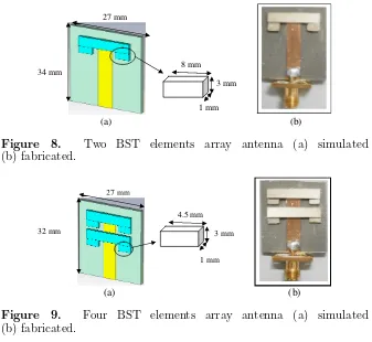
Figure 8. Two BST elements array antenna (a) simulated (b) fabricated.
4.5 mm 3 mm
1 mm 27 mm
32 mm
(a) (b)
Figure 9. Four BST elements array antenna (a) simulated (b) fabricated.
were designed using RO 5880 dielectric-constant substrate material from Rogers Corporation (www.rogerscorp.com) with a dielectric constant of only 2.2.
4.1. Two Elements of BST
The antenna size for the quantity of two elements of BST was 27 mm×34 mm in length and width respectively. The dimensions of each of the BST elements were 8 mm×3 mm, as shown in Figure 8.
4.2. Four Elements of BST
4.3. Six Elements of BST
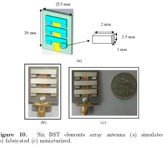
The size of a six element BST antenna can be observed to be smaller than either the two-element or the four-element BST antennas which were 25.5 mm×29 mm in length and width, respectively, and the size of each of the BST elements was 2 mm×2.5 mm. These can be seen in Figure 10. This antenna was fabricated for real-world use, as shown in Figures 10(b) and 10(c). The size of the antenna with BST elements loaded on the antenna was miniaturized, as shown in Figure 10(c), where it is compared with the size of the 20-cent Malaysian currency, which has a diameter of 23.59 mm. The comparison results of both simulated design and measured hardware were completed in order to view the potential radiation performance of this design.
Based on Figures 8, 9, and 10, it was shown that BST dielectric resonators loaded on a microstrip patch were proven to provide a miniature antenna. The results obtained in [38] seemed to indicate lower performance in terms of return loss, gain, and other antenna parameters that are not suitable for use in modern
2 mm
2.5 mm
1 mm 25.5 mm
29 mm
(a)
(c) (b)
wireless communication systems. Thus, BST array antennas met the expectations required by antenna specifications, and they also cost less to produce.
5. TECHNICAL DESIGN PRINCIPLES
The dielectric resonator ceramics were placed on top of the ground side of a microstrip line with line feed method attached. Due to dielectric resonator ceramics mounted on the ground plane, typically, the TE-mode is excited. Perfect magnetic walls are assumed to lie in thex-z
plane, as shown in Figure 7. Thus, it can support TE111, which is
the lowest mode that works well at center frequency of 2.4 GHz, and produce better performance.
For a rectangular dielectric resonator ceramic as was used in this study, TEδ0n and TEδm0 modes cannot exist, i.e., m and n must be
at least 1, because Equations (2) and (3) require that, all the derived fields must be zero if eithermornis zero, in which caseAz also equal to zero [31–35]. Hence, the lowest order mode for the TE case is the TE111mode. The field distribution of a rectangular dielectric resonator
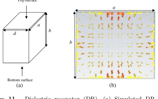
was investigated in our research. Figure 11 shows a dielectric resonator block and the field pattern for the commonly used TE111 mode.
The plot in Figure 11(b) clearly depicts the end-effect at the top and bottom of the resonator. The electric field is strong at the top and bottom surfaces of the DR. This field propagation behavior indicates that, in order to couple effectively to this mode, a port can be placed
Top surface
Bottom surface
d
a b
b
a
(a) (b)
(a) (b)
Figure 12. Field distribution of the BST array antenna at a frequency range of 2.3 GHz to 2.5 GHz. (a) E-field distribution. (b) H-field distribution.
in parallel to the strongest field, i.e., along the vertical axis of the resonator. This technique has been utilized in the design of the BST array antenna.
Figure 12 shows the behavioral characteristics of the electromag-netic waves in the BST array antenna. Figure 12 shows, the BST array antennas are able to transmit or receive radio waves in all directions equally, i.e., they are omni-directional. Added, the fields inside the ar-ray antenna may be used to relate size with operational frequency. By taking the origin at the center of the antenna, perfect magnetic walls are assumed to lie in thex-z plane at y =−b/2 and at y =b/2. Also perfect magnetic walls are assumed to lie in they-zplane atx=−a/2 and x = a/2. Continuity of the tangential fields is enforced at z =h
and, by image theory, atz=−h.
Perfect magnetic walls are assumed along the four surfaces that are parallel to the direction of propagation in the dielectric guide, while the tangential components of the electric and magnetic fields are assumed to be continuous across the two surfaces, perpendicular to the direction of propagation. Thus, it can support TEδmn, where the value δ can be defined as the fraction of a half cycle of the field variation in the z direction; the value δ is given by Equation (2) in which kx is the atmospheric wave number, and d is the length of the rectangular dielectric resonator. The exciting mode, TEδmn, in the rectangular dielectric resonator ceramic can be found by using in following Equations (2) and (3) below, which define the fraction of a half cycle of the field variation in thez direction:
δ = kπx
d
(2)
Az = Bmnsin
³mπx a
´
sin³nπy
b ´
where kx is the atmospheric wave number, and dis the length of the rectangular dielectric resonator’s magnetic vector potential. According to Marcatili’s approximation [35–37], the characteristic equations for the wave numbers, kx andky at TEδmn modes are:
kyb=nπ−2 tan−1
µ ky εkyn
; n= 1,2,3, . . . (4)
where,
ky0 = £(ε−1)k20−ky2
¤1/2
(5)
kxa = mπ−2 tan−1
µ kx kxn
; n= 1,2,3, . . . (6)
where
kx0 =£(ε−1)k20−k2x
¤1/2
(7) where kx0 and ky0 represent decay constants of the field along the x- and y-directions outside the dielectric resonator ceramic. Once the values of kx and ky have been computed for a mode at a given frequency, using Equations (4)–(7), the propagation constant kz can be computed by using the following separation Equation (8):
kx2+k2y+k2z =εk02 (8) where k0 is the free space wave number. Further, from the symmetry
of the structure, it is clear that the characteristic equation for the wave numberskz should be identical to that for the wave numberkx. More specifically, the characteristic equation forkz is given by Equations (9) and (10):
kzc=lπ−2 tan−1
µ kz kzb
; l= 1,2,3, . . . (9)
where
kz0−£(ε−1)k20−k2z
¤1/2
(10) With the characteristic equation ofkx and ky, it is assumed that the dielectric constant of the dielectric resonator ceramic isεeff where
εeff is given by Equation (11)
εeff =ε−
à k2 y k2 x ! (11)
Equations (12) and (13) show the determination of quality factor.
Q = 2πfoε
P (12)
P = −dE
dt (13)
where fo is the resonant frequency, εthe stored energy in the cavity, and P the dissipated power. High quality factor implies that there is no inherent conductor loss in dielectric resonators. This leads to high radiation efficiency of the antenna. HigherQ indicates a lower rate of energy loss relative to the stored energy. One important property of a dielectric material is its permittivity. Permittivity (ε) is a measure of the ability of a material to be polarized by an electric field.
Based on the parallel plate capacitor theory, the capacitance of flat, parallel metallic plates of areaAand separation dis given by the expression below:
C = kxεoxεrxA
d (14)
whereεo is the permittivity of space, andkis the relative permittivity of the dielectric material between the plates. The valuek= 1 indicates that it is for the free space constant value, and when k >1, it is for all the media involved in the measurement.
The surface current distributions of the BST array antenna at resonant frequencies are shown in Figure 13. The BST dielectric resonators loaded on the microstrip patch have resulted in resonance frequencies of 2.3 GHz, 2.4 GHz and 2.5 GHz. On the contrary, Figure 14 shows an antenna without BST dielectric resonators, which results in large current distributions occurring on the surface at a frequency of 2.85 GHz. This frequency is out of the range of the WiMAX and WLAN bands. In order to achieve the desired frequency resonances, we analyzed the WiMAX and WLAN bands antenna from the perspective of the current flow.
The resonance length of the antenna must satisfy the following criteria: λ/4 length of the frequency. Therefore, we inserted BST dielectric resonators on the metallic line feed, which is the area with large current distribution, to satisfy the resonance length and achieve the desired resonance frequencies. Thus, the current flow at the metallic line feed indicates that the BST dielectric resonators can radiate at WiMAX and WLAN bands.
Current distribution at the metal line feed. No current distribution at BST dielectric resonator
Current distribution at the metal line feed. No current distribution at
BST dielectric resonator
(a) (b)
(c)
Figure 13. Surface currents on the BST array antenna at different frequencies (a) 2.3 GHz, (b) 2.4 GHz, (c) 2.5 GHz.
6. PRACTICAL ANTENNA MEASUREMENT
Power measurement applications were conducted to sense multiple power points for a long distance, mechanically moving the sensor further at every step. With the equipment, we managed the power measurement processes, analyzed, computed, and displayed the data.
transmitting antenna must have a beam width just wide enough to cover the test range. Energy transmitted outside this range, will only result in more problems due to multi-path reflections. The preferred method for measuring power is the use of a Spectrum Analyser. This device gives a graphical and precise view of the power received within
Figure 14. Surface current on the antenna without BST dielectric resonators atf = 2.85 GHz.
Tx AUT
AUT
Tx
(a) (b)
(c)
(a) (b)
Figure 16. Power and distance measurement equipment. (a) Power sensor. (b) Power analysis software.
a given frequency range. Therefore, we had to resort to a broadband power sensor, utilizing a diode as a detector.
The distanceSminbetween the transmit antenna and the Antenna
Under Test (AUT) is large enough to be in the far field (Rayleigh Distance). If the sensitivity of the field strength (FS) permits, the distance can be increased to improve the accuracy of the measurement. The transmitting (Tx) antenna will produce a FS at the AUT, that varies with the height of the Tx antenna and AUT. The Tx antenna is placed at a height ofH1, which produces a maximum field strength
at the AUT at height H2. For this, the Tx antenna was placed in
the position closest to the ground and raised until the first maximum FS appeared at the AUT. The positions of the Tx antenna and the AUT were chosen in a manner to minimize the influence of ground and obstacle reflections on the measurements. The antenna range setup was similar to the power measurement setup, as in Figure 15, while the equipment used for the measurement was the Agilent Power Sensor and Power Analysis software, as shown in Figure 16.
Power sensor measurement was tested in a microwave laboratory and anechoic chamber, and the results for the six-element BST array antenna at a distance of 2 and 16 m away from the transmitting antenna are shown in Figures 17(a) and (b) respectively. The noise floor (NF) of the microwave laboratory and anechoic chamber, which was tested, was −52.9 dBm and −45.7 dBm, respectively in the power analysis software. The measurement setup is shown in Figures 15(b) and (c). The radiating power for a BST array antenna seems to have the ability to overcome the NF, as can be seen in Figure 17.
(a) (b)
Figure 17. Radiating power of BST array antenna at various distances in WiMAX and WLAN bands (a) in anechoic chamber (b) in microwave laboratory.
likely in aerospace applications. However, Figure 17(b) implies that signal distortion occurred while the measurements were being taken, especially at the distance of 3 to 6 m from transmitting antenna. Power sensing at these ranges was unstable due to diffraction and reflection of the signal by the nearby furniture. Although radiating power problems occurred, the performance of the BST array antenna was not affect adversely, so the problems that were encountered can be overcome by operating the measurement setup in an outdoor free-space environment.
7. RESONANT FREQUENCY
The proposed antenna was characterized with the help of the simulated and measured results. The resonant frequency of the rectangular TE mode dielectric resonator ceramic array antenna was calculated with by Equation (15), which was described in [5]. This gave a frequency range of 2.25–2.57 GHz withεr= 15.
fo=
3.0×10⁸ µ
εr+ 2
εr
2πp
·
0.27 + 0.36 r 2h + 0.4
³ r 2h
´2¸
(15)
Figure 18. Return loss of both measured and simulated BST array antennas.
minimum return loss frequency from the simulation for the rectangular TE mode dielectric resonator ceramic was found to be 15 MHz or 4.0%. The −10 dB return loss bandwidths were 420 MHz for the simulated and 320 MHz for the measured BST array antenna.
Figure 18 shows the comparison between simulated and measured return loss after conversion into log magnitude in dB. The result shows the resonant frequency in the range of 2.30 to 2.50 GHz. It can be seen clearly that the return loss of the three different numbers of elements of TE-mode, rectangular BST fell between−10 dB and−19 dB, which indicates that more than 90% of the signal was radiated through these antennas.
8. RADIATION PATTERN
The radiation pattern measurement was performed in an anechoic chamber, as shown in Figure 19. An anechoic chamber was used to minimize the reflections during the measurement, in order to obtain optimum and realistic results.
The field strength was measured at a fixed distance while the antenna under test was rotated through 360 degrees in theta and phi axes, to produceE-field and H-field radiation pattern measurements. The antenna under test (AUT) is connected to the transmitting antenna stand in this measurement setup, and the receiving antenna used is a dual polarized horn antenna. The horn antenna is fed with an input power of 1 mW from the first port of the PNA, while an AUT transmitted power is analyzed through the second port of the PNA. To record the measurement data and radiation patterns, Passive Measurement software, integrated with the anechoic chamber, was used. Measurement data were collected at specific points in order to determine the radiation pattern. The software calculated the antenna gain, directivity and efficiency and it provided 2D and 3D measurement results. Test results of the relative field strength for each angle and the displayed radiation pattern were compiled into a plot [35].
Table 2 shows the results for the matched resonances of the BST array antennas for the 2.3 to 2.5 GHz frequency band at an impedance
Receiving Antenna (Tx): Double Rigid Waveguide Horn
Transmitting Antenna (Rx):
BST Array Antenna
Table 2. Experimental results for gain, directivity, and transmission power of BST array antennas.
Parameters
Number of BST elements
two elements four elements six elements 2.3 GHz 2.4 GHz 2.5 GHz 2.3 GHz 2.4 GHz 2.5 GHz 2.3 GHz 2.4 GHz 2.5 GHz Gain (dB) 4.501 4.509 4.512 5.000 5.002 5.010 6.117 6.119 6.123 Directivity
(dBi) 5.021 5.025 5.028 6.043 6.046 6.053 7.076 7.080 7.082 Transmission
Power (dBm) 27.15 27.22 27.29 27.39 27.40 27.42 27.46 27.48 27.51
of 50 Ω. This shows that increasing the number of BST elements allows the realization of larger gain and directivity, while maintaining antenna miniaturization. The low conduction loss experienced by the BST dielectric resonator results in improved radiation efficiency for the antenna. Table 2 shows that the largest gain of 6.123 dB and the largest directivity of 7.082 dBi occur with the six-element BST antenna. This shows about 35% increase in both gain and directivity as the numbers of elements are increased from 2 to 6. As the numbers of elements are increased from 2 to 4 and 4 to 6, the gain and directivity are increased to about 11% and 22% respectively. Hence, the proposed antenna will be useful for high gain and high directivity systems that can transmit and receive maximum signals.
Transmission power also was observed by the Passive software and is shown in Table 2. The results show that, compared to conventional Wi-Fi indoor router antennas that operate in the range of 2.4–2.4835 GHz, less power consumption is needed for signal transmission [36]. The attenuation for this BST array antenna was lowered due to the high dielectric constant and low dielectric loss of the dielectric resonator materials.
(i)
(iv) (iii)
(ii)
(a)
(i) (ii) (iii)
(b)
Figure 20. Radiation pattern in 3D view at 2.3–2.5 GHz (a) simulated (i) two elements of BST; (ii) four elements of BST; (iii) six elements of BST; (iv) side view; (b) measured (i) two elements of BST; (ii) four elements of BST; (iii) six elements of BST.
Based on the observation of the radiation pattern, it can be said that the antenna is radiating in the vertical axis with a gain of 6.123 dB with six BST elements, as compared to 4.512 dB and 5.010 dB for two-and four-element BST antennas, respectively.
(a) (b)
Figure 21. Elevation pattern (H-field) at Azimuth = 90◦. (a) simulated, (b) measured.
(a) (b)
Figure 22. Azimuth pattern (E-field) at Elevation = 90◦. (a) simulated (b) measured.
9. CONCLUSIONS
In this paper, the application of rectangular barium strontium titanate (BST) as dielectric resonator ceramic antenna in array form that was comprised of two, four and six elements of BST was proposed and successfully accomplished. The TE mode rectangular array antenna exhibited acceptable bandwidths, reflections and radiation characteristics for WLAN and WiMAX applications. By taking into account all the details of each component, including dimensions and dielectric constant values, the antennas performed better with very high gain, which also fulfilled the expectation of this research. The expectation of achieving higher gain with an increasing number of BST in this TE-mode structure antenna was successful and such an antenna can be utilized in real-world applications with the fabricated six-element BST array antenna. The utilization of TE-mode rectangular dielectric resonator ceramic in the antenna improved the performance of the antenna with better return loss lower than −10 dB throughout the range frequencies from 2.30 to 2.50 GHz. The branching strips with smart materials used to replace the copper plate were verified, confirming that the antenna could radiate appropriately; further, it performed much better than other antennas in terms of gain and efficiency.
At the present time, antenna miniaturization is of great concern due to the physical benefits and the dielectric resonator ceramic antenna design satisfies this need. Even though the proposed design suffers from all same effects as other antennas, i.e., sag in the pattern shape, reduction of hardware measurement bandwidth and return loss, it is sufficiently compact, and it has the proper impedance bandwidth for use in WLAN and WiMAX. Ultimately, BST array antennas were experimentally tested to compose multiple advantages in wireless antenna system, including smaller size, higher radiation coefficient properties, wider bandwidth, and far distant radiation power as compared to available microstrip antennas. The proposed and tested antenna system provided approximately 20 to 50% better performance, as mentioned earlier in the discussions of our test results.
optimized radiation patterns for WiMAX and WLAN applications. In addition, different shapes of dielectric resonator ceramics should also be investigated, e.g., circular, hemispherical, diamond, and triangular shapes. Eventually, our goals for BST array antennas are to be able to offer miniaturized antennas that provide high efficiency, large bandwidth, low profile, low production cost, and low conductor loss that are potentially more efficient for modern wireless systems than the conventional microstrip antennas.
REFERENCES
1. Al-Zoubi, A. S., A. A. Kishk, and A. W. Glisson, “Analysis and design of a rectangular dielectric resonator antenna fed by dielectric image line through narrow slots,” Progress In Electromagnetics Research, Vol. 77, 379–390, 2007.
2. Ain, M. F., S. I. S. Hassan, J. S. Mandeep, M. A. Othman, B. M. Nawang, S. Sreekantan, D. Hutagalung, and A. Z. Ahmad, “2.5 GHz BaTIO3 dielectric resonator antenna,” Progress In Electromagnetics Research, Vol. 76, 201–210, 2007.
3. Fayad, H. and P. Record, “Multi-feed dielectric resonator antenna with reconfigurable radiation pattern,” Progress In Electromagnetics Research, Vol. 76, 341–356, 2007.
4. Zandi, O., Z. Atlasbaf, and K. Forooraghi, “Flat multilayer dielectric reflector antennas,” Progress In Electromagnetics Research, Vol. 72, 1–19, 2007.
5. Zainud-Deen, S. H., H. A. Malhat, and K. H. Awadalla, “A single feed cylindrical superquadric dielectric resonator antenna for circular polarization,”Progress In Electromagnetics Research, Vol. 85, 409–424, 2008.
6. Long, S. A., M. W. McAllister, and L. C. Shen, “The resonant cylindrical dielectric cavity antenna,” IEEE Trans. Antenna Propagate, Vol. 31, 406–421, May 1983.
7. Tikhonov, V. V., D. A. Boyarskii, O. N. Polyakova, A. L. Dzardanov, and G. N. Goltsman, “Radiophysical and dielectric properties of ore minerals in 12–145 GHz frequency range,”
Progress In Electromagnetics Research B, Vol. 25, 349–367, 2010. 8. Tadjalli, A., A. Sebak, and T. Denidni, “Resonance frequencies and far field patterns of elliptical dielectric resonator antenna: Analytical approach,” Progress In Electromagnetics Research, Vol. 64, 81–98, 2006.
antenna for short range wireless communication,” Progress In Electromagnetics Research Letters, Vol. 19, 19–30, 2010.
10. Hasar, U. C., “Unique permittivity determination of low-loss dielectric materials from transmission measurements at microwave frequencies,”Progress In Electromagnetics Research, Vol. 107, 31– 46, 2010.
11. Li, E., Z.-P. Nie, G. Guo, Q. Zhang, Z. Li, and F. He, “Broadband measurements of dielectric properties of low-loss materials at high temperatures using circular cavity method,” Progress In Electromagnetics Research, Vol. 92, 103–120, 2009.
12. Hasar, U. C. and O. Simsek, “An accurate complex permittivity method for thin dielectric materials,”Progress In Electromagnet-ics Research, Vol. 91, 123–138, 2009.
13. Jamaluddin, M. H., R. Sauleau, X. Castel, R. Benzerga, L. Le Coq, R. Gillard, and T. Koleck, “Design, fabrication and characterization of a dielectric resonator antenna reflect array in ka-band,”Progress In Electromagnetics Research B, Vol. 25, 261– 275, 2010.
14. Zhai, J. W., X. Yao, and X. G. Cheng, “Direct-current field dependence of dielectric properties in B2O3-SiO2 glass doped
Ba0.60Sr0.40TiO3 ceramic,” J. Mater. Sci., Vol. 37, 3739–3745,
2002.
15. Wei, X. Y. and X. Yao, “Nonlinear dielectric properties of barium strontium titanate ceramics,”Materials Science and Engineering B, Vol. 99, Nos. 1–3, 74–78, May 25, 2003.
16. Song, Y. and A. R. Sebak, “Radiation pattern of aperture coupled prolate hemispheroidal dielectric resonator antenna,”Progress In Electromagnetics Research, Vol. 58, 115–133, 2006.
17. Sreekantan, S., A. F. M. Noor, Z. A. Ahmad, R. Othman, and A. West, “Structural and electrical characteristics of crystalline barium titanate synthesized by low temperature aqueous method,” Journal of Materials Processing Technology, Vol. 195, Nos. 1–3, 171–177, 2008.
18. Brankovic, G., Z. Brankovic, M. Goes, C. Paiva-Santos, M. Cilense, J. Varela, and E. Longo, “Barium strontium titanate powders prepared by spray pyrolysis,” Materials Science and Engineering: B, Vol. 122, No. 2, 140–144, 2005.
20. Yang, Z., R. Gu, L. Wei, and H. Ren, “Phase formation, microstructure and dielectric properties of Sr 0.53Ba0.47Nb2-xTaxO6 ceramics,” Journal of Alloys and Compounds, Vol. 504, No. 1, 211–216, 2010.
21. Gervais, C., D. Veautier, M. E. Smith, F. Babonneau, P. Belleville, and C. Sanchez, “Solid state 47, 49Ti, 87Sr and 137Ba NMR characterisation of mixed barium/strontium titanate perovskites,”
Solid State Nuclear Magnetic Resonance, Vol. 26, Nos. 3–4, 147– 152, 2004.
22. Wang, X. H., R. Z. Chen, Z. L. Gui, and L. T. Li, “The grain size effect on dielectric properties of BaTiO3 based ceramics,” Materials Science and Engineering B, Vol. 99, 199, 2003.
23. Huang, X.-D., X.-H. Jin, and C.-H. Cheng, “Novel impedance matching scheme for patch antennas,”Progress In Electromagnet-ics Research Letters, Vol. 14, 155–163, 2010.
24. De Flaviis, F., N. G. Alexopoulos, and O. M. Stafosudd, “Plarlar microwave integrated phased shifter design with high purity ferroelectric material,” IEEE Trans. Microwave Theory Tech., Vol. 45, 963–969, 1997.
25. Saed, M. and R. Yadla, “Microstrip-fed low profile and compact dielectric resonator antennas,” Progress In Electromagnetics Research, Vol. 56, 151–162, 2006.
26. Sangiovanni, A., J. Y. Dauvignac, and C. Pichot, “Stacked dielectric resonator antenna for multifrequency operation,”
Microwave and Optical Technology Letters, Vol. 18, 303–306, Jul. 1998
27. Rao, Q., T. A. Denidni, A. R. Sebak, and R. H. Johnston, “On improving impedance matching of a CPW fed low permittivity dielectric resonator antenna,” Progress In Electromagnetics Research, Vol. 53, 21–29, 2005.
28. Kishk, A. A. and A. W. Glisson, “Bandwidth enhancement for split cylindrical dielectric resonator antennas,” Progress In Electromagnetics Research, Vol. 33, 97–118, 2001.
29. Wu, J. Y., C. Y. Huang, and K. L. Wong, “Low-profile, very high permittivity dielectric resonator antenna excited by a coplanar waveguide,” Microw. Opt. Technol. Lett., Vol. 22, 96–97, Jan. 1, 1999.
30. Qian, Z. H., K. W. Leung, and R. S. Chen, “Analysis of circularly polarized dielectric resonator antenna excited by a spiral slot,”
31. Biancotto, C. and P. Record, “Dielectric EBG corner reflector antenna,” Journal of Electromagnetic Waves and Applications, Vol. 24, Nos. 14–15, 2107–2118, 2010.
32. Wang, Z., P. Li, R. Xu, and W. Lin, “A compact X-band receiver front-end module based on low temperature co-fired ceramic technology,”Progress In Electromagnetics Research, Vol. 92, 167– 180, 2009.
33. Weng, C. C., C. F. Chang, and S. J. Chung, “Development of a compact low-temperature co-fired ceramic antenna front-end module,” IEEE Trans. Microw. Theory Tech., Vol. 56, No. 11, 2483–2492, Nov. 2008.
34. Karonis, G. J., D. I. Kaklamani, and N. K. Uzunoglu, “Accurate analysis of a cylindrical dielectric resonator mounted on a grounded dielectric substrate,” Progress In Electromagnetics Research, Vol. 23, 187–219, 1999.
35. Atenlab Corporation, Microwave Product Measurement Descrip-tion, http://www.atenlab.com.tw/.
36. FCC Rules for Unlicensed Wireless Equipment Operating in the ISM Bands, http://www.wisp-router.com/page.php?11.
37. Li, X., L. Yang, S.-X. Gong, and Y.-J. Yang, “Bidirectional high gain antenna for WLAN applications,” Progress In Electromagnetics Research Letters, Vol. 6, 99–106, 2009.
38. Van Bladel, J., “On the resonances of a dielectric resonator of very high permittivity,” IEEE Trans. Microwave Theory Tech., Vol. 23, 199–208, 1975.
39. Zhou, S.-G., J.-L. Guo, Y.-H. Huang, and Q.-Z. Liu, “Wideband and omni-directional for antenna and DVB/GSM applications,”
Journal of Electromagnetic Waves and Applications, Vol. 23, No. 16, 2143–2151, 2009.
40. Kong, J. A., Electromagnetic Wave Theory, Wiley-Interscience, New York, 1986.
41. Kajfez, D. and P. Guillon, Dielectric Resonators, Artech House, Norwood, MA, 1986.
42. Wang, J. Y., X. Yao, and L. Y. Zhang, “Preparation and dielectric properties of barium strontium titanate glass-ceramics sintered from sol-gel derived powders,” Vol. 30, No. 7, 1749–1752, 2004. 43. Marcatili, E. A. J., “Dielectric rectangular waveguide and
directional couplers for integrated optics,” Bell Syst. Tech. J., Vol. 48, 2071–2102, 1969.
45. Gangwar, R. K., S. P. Singh, and D. Kumar, “A modified fractal rectangular curve dielectric resonator antenna for WiMAX application,” Progress In Electromagnetics Research C, Vol. 12, 37–51, 2010.
46. Zainud-Deen, S. H., S. I. El-Doda, K. H. Awadalla, and H. A. Sharshar, “The relation between lumped-element circuit model for cylindrical dielectric resonator and antenna parameters using MBPE,” Progress In Electromagnetics Research M, Vol. 1, 79–93, 2008.
47. Hashim, A. M., “Development of microstrip patch array antenna wireless local area network (WLAN),” ETRI Journal, Vol. 35, No. 5, Oct. 2010.
48. Zubir, F., M. K. A. Rahim, O. B. Ayop, and H. A. Majid, “Design and analysis of microstrip reflect array antenna with Minkowski shape radiating element,” Progress In Electromagnetics Research B, Vol. 24, 317–331, 2010.
49. Sreekantan, S., Y. K. Ling, Z. A. Ahmad, M. F. Ain, M. B. Othman, and S. I. S. Hassan, “Simulation and experimental investigations on rectangular, circular and cylindrical dielectric resonator antenna,” Progress In Electromagnetics Research C, Vol. 7, 151–166, 2009.
50. Tze-Meng, O., K. G. Tan, and A. W. Reza, “A dual-band omni-directional microstrip antenna,” Progress In Electromagnetics Research, Vol. 106, 363–376, 2010.
51. Mazinani, S. M. and H. R. Hassani, “A novel omnidirectional broadband planar monopole antenna with various loading plate shapes,”Progress In Electromagnetics Research, Vol. 97, 241–257, 2009.
52. Farahat, A. E., K. F. A. Hussein, and N. M. El-Minyawi, “Finite length omni-directional cylindrical spatial filters,” Progress In Electromagnetics Research B, Vol. 24, 79–101, 2010.