i
HVAC MONITORING (TEMPERATURE) AND CONTROLLING (VALVE/DAMPER) SYSTEM
AB RAZAK BIN ARIFFIN
Report submitted in partial fulfilment of the requirements for the award of Bachelor of Electronic and Computer Engineering
Faculty of Electronic and Computer Engineering UNIVERSITI TEKNIKAL MALAYSIA MELAKA
ii
UNIVERSTI TEKNIKAL MALAYSIA MELAKA
FAKULTI KEJURUTERAAN ELEKTRONIK DAN KEJURUTERAAN KOMPUTER
BORANG PENGESAHAN STATUS LAPORAN PROJEK SARJANA MUDA II
Tajuk Projek : …HVAC MONITORING AND CONTROLLING SYSTEM
Sesi Pengajian
: 1 5 / 1 6
Saya AB RAZAK BIN ARIFFIN . (HURUF BESAR)
mengaku membenarkan Laporan Projek Sarjana Muda ini disimpan di Perpustakaan dengan syarat-syarat kegunaan seperti berikut:
1. Laporan adalah hakmilik Universiti Teknikal Malaysia Melaka.
2. Perpustakaan dibenarkan membuat salinan untuk tujuan pengajian sahaja.
3. Perpustakaan dibenarkan membuat salinan laporan ini sebagai bahan pertukaran antara institusi pengajian tinggi.
4. Sila tandakan ( √ ) :
SULIT* *(Mengandungi maklumat yang berdarjah keselamatan atau kepentingan Malaysia seperti yang termaktub di dalam AKTA RAHSIA RASMI 1972)
TERHAD** **(Mengandungi maklumat terhad yang telah ditentukan oleh organisasi/badan di mana penyelidikan dijalankan)
TIDAK TERHAD
Disahkan oleh:
________________________ ___________________________________
(TANDATANGAN PENULIS) (COP DAN TANDATANGAN PENYELIA)
iii
“I hereby declare that the work in this project is my own except for summaries and quotations which have been duly acknowledge.”
Signature : ... Author : AB RAZAK BIN ARIFFIN
iv
“I acknowledge that I have read this report and in my opinion this report is sufficient in term of scope and quality for the award of Bachelor of Electronic Engineering (Industrial Electronics/ Computer Engineering/ Electronic Telecommunication/ Wireless
Communication)* with Honours.”
Signature : ... Supervisor’s Name : EN MOHD KHANAPIAH BIN NOR
v
ACKNOWLEDGEMENT
I would like to express my gratitude and appreciation to all those who gave me the possibility to complete this report. A special thanks to our final year project coordinator, PM. Dr. Kok Siew Leong, whose help, stimulating suggestions and encouragement, helped me to coordinate my project especially in writing this report.
I would also like to acknowledge with much appreciation the crucial role of the staff of Wireless Laboratory, who gave the permission to use lab to carry the project and get all required machinery and the necessary material to complete this project.
A special thanks goes to my friend under same supervisor, Ikhwan Hamiz Bin Zulkefly, Khairul Anwar Bin Kamal and Ahmad Syakir Bin Saarani, who help me to assemble the parts and gave suggestion about this project
vi
ABSTRACT
“Design of HVAC monitoring and controlling system to control the air flow with controllable damper and monitoring temperature”
Abstract of Project:
HVAC monitoring and controlling systems are small but significant part in any industrial application. Increase demand of HVAC usage is main motivation behind this project beside the way they use the HVAC not suitable way that make the people not comfort. The main feature of this project is all about a designing the HVAC prototype with monitoring and controlling system with effective cost and reliable valve to control the air flow.
vii
ABSTRAK
"Rekaan pemantauan HVAC dan sistem kawalan untuk mengawal aliran udara dengan penampan boleh dikawal dan memantau suhu"
Abstrak Projek
Pemantauan HVAC dan sistem kawalan adalah kecil tetapi penting dalam apa-apa bahagian didalam kegiatan industri. Peningkatan permintaan penggunaan HVAC adalah motivasi utama di sebalik projek ini di samping cara mereka menggunakan HVAC secara yang tidak sesuai yang membuat orang tidak selesa. Ciri utama projek ini adalah tentang mereka satu bentuk prototaip HVAC dengan system pemantau dan pengawalan dengan kos efektif dan injap dipercayai untuk mengawal aliran udara.
viii
TABLE OF CONTENT
CHAPTER TITLE PAGE
PROJECT TITLE i
REPORT STATUS VERIFICATION FORM ii
DECLARATION iii
SUPERVISOR DECLARATION iv
ACKNOWLEDGEMENT v
ABSTRACT vi
ABSTRAK vii
TABLE OF CONTENT viii
LIST OF TABLES xi
LIST OF FIGURES xi
LIST OF APPENDICES xiii
I INTRODUCTION
1.1 Introduction 1
1.2 Project Objective 3
1.3 Problem Statement 3
1.4 Project Scope 3
1.5 Overview of Report 4
ix
2.1 The Theory of Control System 5
2.2 Feedback Control System 6
2.3 Servo Motor 7
2.4 Fundamental of HVAC Control 10 2.5 Arduino Uno Microcontroller 14
2.6 Arduino Ethernet Shield 17
2.7 Temperature Sensor 18
III PROJECT METHODOLOGY
3.1 System Overview 22
3.2 Project Flowchart 23
3.3 Block Diagram 27
3.4 Project Planning 28
IV RESULTS AND DISCUSSION
4.1 HVAC controlling system (damper) 29
4.2 HVAC monitoring system (temperature) 30
4.3 HVAC monitoring and controlling system 31 4.4 GUI for monitoring and controlling HVAC system 33 4.5 Prototype for monitoring and
Controlling HVAC system 34
x
4.7 Project Discussion 41
V CONCLUSION AND RECOMMENDATION
5 Conclusion 42
6 Recommendation 42
REFERENCES 43
APPENDIX A 45
APPENDIX B 47
APPENDIX C 49
APPENDIX D 52
xi
LIST OF TABLES
NO. TITLE PAGE
1 Servo Motor Specification 9
2 Arduino Uno Specification 16
3 Temperature reading for all degree of valve 35
LIST OF FIGURES
NO. TITLE PAGE
2.1.1 Control System 6
2.2.1 Feedback Control System Diagram 6
2.3.1 The concept of Servo System 7
2.3.2 Servo motor diagram 9
xii
2.4.1 Chilled Water System with Water Cooled Condenser 12
2.4.2 HVAC damper diagram 13
2.4.3 Damper inside HVAC 14
2.5.1 Arduino Uno Board 14
2.5.2 Arduino Uno Schematic Diagram 15
2.6.1 Arduino Ethernet Shield Diagram 17 2.6.2 Arduino Ethernet Shield Schematic Diagram 18
2.7.1 LM35 diagram 20
2.7.2 LM35 Schematic diagram 21
3.2.1 Main flowchart 23
3.2.2 Control flowchart 24
3.2.3 Monitor flowchart 25
3.2.4 GUI flowchart 26
3.3.1 Block Diagram 27
3.4.1 Project Planning 28
4.1.1 Switch controlled servo 29
4.1.2 Switch control servo schematic view 30
4.2.1 LM35 circuit design 30
4.2.2 LM35 schematic diagram 31
4.3.1 Servo motor and temperature sensor LM35 circuit diagram 32 4.3.2 Servo motor and temperature sensor
LM35 schematic diagram 32
4.4.1 GUI for monitoring and controlling HVAC system 33
xiii
4.6.1 Temperature reading before HVAC turn on at 0° 35
4.6.2 Result of GUI at degree 0 before HVAC turn on 36 4.6.3 Temperature sensor reading after HVAC turn on at 0° 37 4.6.4 Result GUI at degree 0 after HVAC turn on 37 4.6.5 Temperature sensor reading at valve 90° 38 4.6.6 Result GUI at degree 90 after HVAC turn on 38 4.6.7 Temperature sensor reading at 180° 39 4.6.8 Result of GUI at degree 180 after HVAC turn on 40
LIST OF APPENDICES
NO. TITLE PAGE
A ARDUINO CODING FOR SWITCH
CONTROLLED MOTOR (DAMPER/VALVE) 45
B ARDUINO CODING FOR TEMPERATURE SENSOR
(MONITORING) 47
C ARDUINO CODE FOR MONITORING AND
CONTROLLING HVAC SYSTEM 49
D ARDUINO CODING FOR SEND TEMPERATURE
SENSOR (MONITORING) READING TO DATABASE 52
1
CHAPTER 1
1 INTRODUCTION
1.1 PROJECT BACKGROUND
HVAC is short for heating, ventilation, and air conditioning. The system is used to provide heating and cooling services to buildings. HVAC systems have become the required industry standard for construction of new buildings. Before the creation of this system, the three elements were usually split between three or more devices.
Control system is a system, gadget or set of gadget that manages, aim, coordinates or directs the conduct of different gadgets that we can control its conduct or attributes by utilizing different gadgets or systems. Mastascusa (1999) said that while controlling a system, the main thing to know is the thing that the system itself need to control and how well it is getting along. [1]
The control valve/damper is one of the important part in control the airflow of HVAC. The control valve (damper) is something that we can adjust to get the airflow that we desired. In this case the valve area that we must change to get the appropriate airflow. So, the accurate airflow must be adjust using the valve (damper) to make sure the airflow in the valve will be accurate.
2
empower the following of obvious subjective and quantitative information and makes an interpretation of it into profitable administration data. The system needs to in this manner be available, guaranteeing straightforwardness and advance the sharing and trading of encounters and lessons learned and make an interpretation of this into restorative activity.
The monitoring system is important for decrease electrical usage. Most people want to decrease something firstly they must monitor what the problem. In HVAC the monitoring system, it only can use temperature monitoring system because HVAC is about air conditioning. If people work during evening they not need temperature too low from HVAC like people that work at the morning. So they can decrease the electrical usage because more HVAC temperature increase more energy used.
This project system is run circuit that can control the temperature reading and collect the data in real time which using software that can analyze the data in real time. Before the software can analyze the data, must have some circuit can control the air flow out and device that can grab the data from sensor and convert into a data that PC (Personal Computer) can understand or read which, the device is Arduino Uno. Function of Arduino Uno is to convert the analogue signal to digital signal (which can understand by PC)
3
1.2 PROBLEM STATEMENT
The problem statement in this project is the controlling and monitoring of HVAC temperature in university is very important because it can affect the mood student for study. Student need comfort place to study, if the place very hot or too cool, it makes the place be not comfort for student to study. The Graphical User Interface (GUI) is developing using MATLAB. With this GUI, user can control and monitor the change of temperature through user own personal computer (PC).
1.3 OBJECTIVES
This document proposed a design of low cost monitoring and controlling HVAC. I have identified 4 major objectives must meet in development this system.
1. To model the prototype of HVAC.
2. To design GUI using MATLAB for monitoring the change of temperature.
3. To developed HVAC temperature controlling system using low cost. 4. To develop sensor system which capable to monitoring temperature in
real-time
1.4 SCOPE OF PROJECT
Several scope of project is:
1. The hardware part of controlling HVAC temperature system will be designed and development.
4
3. The sensor part should capable to monitor temperature in real time. 4. The working controlling and monitoring HVAC system will be tested
in related industrial application.
1.5 OVERVIEW OF REPORT
5
CHAPTER 2
2 LITERATURE REVIEW
2.1 THE THEORY OF CONTROL SYSTEM
Control systems are a basic piece of present day society. Various applications are surrounding us: The rockets fire, and the space transport lifts off to earth circle; in sprinkling cooling water, a metallic part is consequently machined; an independently directed vehicle conveying material to workstations in an aviation get together plant skims along the floor looking for its destination. These are only a couple of illustrations of the naturally controlled systems that we can make. [2]
We are by all account not the only makers of naturally controlled systems; these systems likewise exist in nature. Inside of our own bodies are various control systems, for example, the pancreas, which directs our glucose. In time of ''battle or flight,'' our adrenaline increments alongside our heart rate, creating more oxygen to be conveyed to our cells.
Our eyes take after a moving article to keep it in perspective; our hands get a handle on the item and place it definitely at a foreordained area. Indeed, even the nonphysical world has all the earmarks of being naturally directed(Nise, 2011).
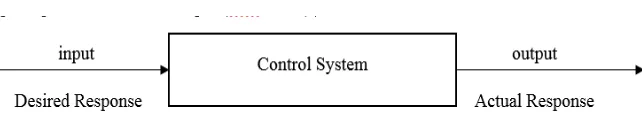
Control System Definition
6
Figure 2.1.1: Control System
2.2 FEEDBACK CONTROL SYSTEM (Closed loop)
By using the closed-loop system, those errors made by the disturbances can be overcome(Nise, 2011). This also is an advantage of close-loop system compare to open-loop system which can’t correct the errors made by the disturbance and directly only take command from the input we enter. The best example of the open-loop system is on the washing machine application. Maybe we can set how long the operation and what type of fabrics we want to clean, but the output which is the cleanliness of the clothes, we can’t measure it. The term of ‘closed-loop’ also is referred as the feedback control action in order to decrease the error of the system (Ogata, 2010).
The figure 2 below shows how the sensor reacted as the feedback action as its measure the output value. (Ogata, 2010) also said but their certain case whereas there is no disturbance and using time as its base, it’s more reliable to use open-loop system. We can see this application on traffic light system as example. In traffic lights system, actually the computer will control the sequences of lights displayed at a cross-road to ensure that cars do not crash. Additionally, the computer operates a pedestrian crossing to let pedestrians cross the road when a button is pressed. [3]
7
2.3 SERVO MOTOR
Servo is a term which applies to capacity or task. The function, or errand, of servo can be described as follows. A command signal which issued from the client interface panel comes into the servo's "positioning controller". The positioning controller is the gadget which stores data about different jobs or assignments. It has been modified to active the motor/load (change speed/position)
Figure 2.3.1: The concept of Servo System
The command signal then goes into the servo control area. The servo control takes this low level power signal and increases, or amplifies, the power up to certain levels to actually result in movement of the servo motor/load.
These low level power signals must be amplified. The higher voltage levels are needed to turn the servo motor at certain higher current and higher speed levels are required to provide torque to move heavier loads.
8
As power is connected onto the servo motor, the load starts to move . . . speed and position changes. As the load moves, so does some other "device" move. This other "device" is either a tachometer, resolver or encoder (giving a signal which is "sent back" to the controller). This "feedback" signal is informing the positioning controller whether the motor is doing the proper job.
The positioning controller looks at this feedback signal and figure out if the load is being moved properly by the servo motor; and if not, then the controller makes appropriate corrections. The controller then outputs a signal to apply more voltage onto the servo motor to increase speed until the feedback signal equals the command signal. Therefore, a servo involves several devices. It is a system of devices for controlling some item (load). The item (load) which is controlled (regulated) can be controlled in any manner, i.e. position, direction, speed. The speed or position is controlled in relation to a reference (command signal), as long as the proper feedback device (error detection device) is used. The feedback and command signals are compared, and the corrections made. Thus, the definition of a servo system is, that it consists of several devices which control or regulate speed/position of a load. [4] TowerPro MG995 servo motor
The unit comes complete with 30cm wire and 3 pin 'S' type female header connector that fits most receivers, including Futaba, JR, GWS, Cirrus, Blue Bird, Blue Arrow, Corona, Berg, Spektrum and Hitec
9
Figure 2.3.2: Servo motor diagram
Specification
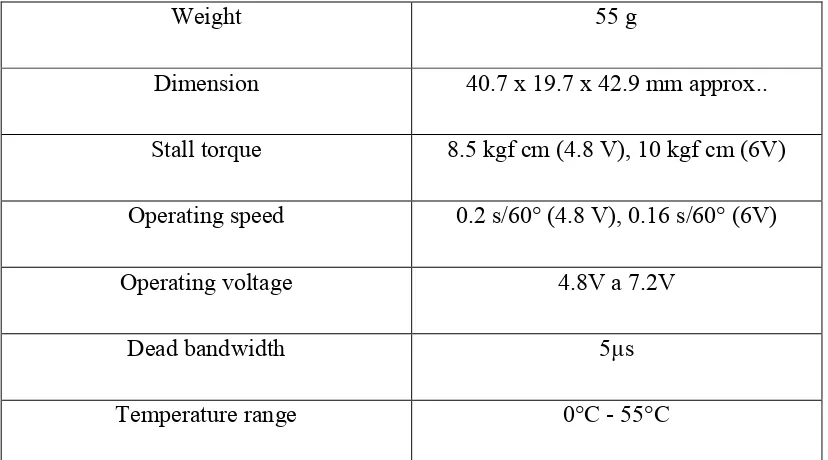
Table 1: Servo motor specification
Weight 55 g
Dimension 40.7 x 19.7 x 42.9 mm approx.. Stall torque 8.5 kgf cm (4.8 V), 10 kgf cm (6V) Operating speed 0.2 s/60° (4.8 V), 0.16 s/60° (6V)
Operating voltage 4.8V a 7.2V
Dead bandwidth 5µs
10
Figure 2.3.3: Servo motor connection
2.4 FUNDAMENTAL OF HVAC CONTROL
HVAC is short for heating, ventilation, and air conditioning. The system is used to provide heating and cooling services to buildings. HVAC systems have become the required industry standard for construction of new buildings. Before the creation of this system, the three elements were usually split between three or more devices. (business dictionary)
HVAC System
HVAC systems are delegated either independent unit bundles or as focal systems. Unit bundle depicts a solitary unit that changes over an essential vitality source (power or gas) and gives last warming and cooling to the space to be adapted. Illustrations of independent unit bundles are housetop HVAC systems, cooling units for rooms, and aerial warmth pumps. With focal systems, the essential transformation from fuel, for example, gas or power happens in a focal area, with some type of warm vitality dispersed all through the building or office. Focal systems are a mix of focal supply subsystem and numerous end use subsystems. There are numerous varieties of consolidated focal supply and end use zone systems.
11
subsystems can be fan frameworks or terminal units. On the off chance that the end use subsystems are fan frameworks, they can be single or numerous zone sort. The numerous end use zone frameworks are blending boxes, typically called VAV boxes.
Another combination central supply and end use zone system is a central chiller and boiler for the conversion of primary energy, as well as a central fan system to delivery hot and/or cold air. The typical uses of central systems are in larger, multi-storied buildings where access to outside air is more restricted. Typically, central systems have lower operating costs but have a complex control sequence. (A. Bhatia, Fundamental of HVAC)
How does central air-conditioning system work?
Cooling Cycle (chilled water system): The supply air, which is around 20° F cooler than the air in the adapted space, leaves the cooling loop through the supply air fan, down to the ventilation work and into the conditional space. The cool supply air grabs heat in the conditional space and the hotter air advances into the arrival air pipe back to the air taking care of unit. The arrival air blends with outside air in a blending chamber and experiences the channels and cooling loop. The blended air surrenders its warmth into the chilled water tubes in the cooling loop, which has balances connected to the tubes to encourage heat exchange. The cooled supply air leaves the cooling loop and the air cycle rehashes. The chilled water circling through the cooling curl tubes, in the wake of getting warmth from the blended air, leaves the cooling loop and experiences the chilled water return (CHWR) channel to the chiller's evaporator. Here it surrenders the warmth into the refrigeration framework. The recently "chilled" water leaves the evaporator and is pumped through the chilled water supply (CHWS) piping into the cooling loop consistently and the water cycle repeats.