404
MAGNETIC LEVITATION TRAINING KIT FOR TEACHING BASIC
ELECTRICAL CONTROL SYSTEM COURSES
Mohd Firdaus bin Mohd Ab. Halim
1,a*, Muhammad Sharil bin Yahaya
2,b, Zulkifli Bin Ibrahim
3,c, Mohd
Farriz bin Hj Md Basar
4,d, Mohd Razali Sapiee
5,e, Suziana Binti Ahmad
6,f,
Che Wan Mohd Faizal bin Che Wan Mohd Zalani
7,g,
Fadzilah binti Salim
8,h, Aminurrashid Noordin
9,i, Norliana binti Ibrahim
10,j1,2,3,4,5,6,7,8,9Faculty of Engineering Technology, Universiti Teknikal Malaysia Melaka, Hang Tuah Jaya,
76100 Durian Tunggal, Melaka, Malaysia. Email: [email protected], [email protected], c
[email protected], [email protected], [email protected], [email protected], g
[email protected], [email protected], [email protected], 10
Kuala Pilah Matriculation
j
Abstract—In this paper, we propose a training kit for developing a system to assist basic electrical control courses to the undergraduate students of Electrical Engineering or Electrical Engineering Technology. We present magnetic levitation hardware demonstrating a load hanging in the air with the help of electromagnetic coil. The students are provided with unassembled training kit project where they will use it to achieve several learning outcome. Technical data of the system is given along with a basic instruction manual as benchmark for the training kit. The magnetic levitation kits provide an open-ended design problem such as designing a sensor, load, closed loop feedback system and a lot more. The training kit is alter made to provide exciting and excellent teaching tools for controls system subject unlike the conventional trainer module.
KeywordsüMagnetic Levitation, Teaching, Electrical Control
Assembly.
I.INTRODUCTION
The career of a lecturer nowadays have become more challenging as they are required to produce learning objects in teaching and learning process. In teaching basic electrical control system courses, there are many conventional plug and play trainer modules in the market but rarely we found a training kit where the students are able to experience the assembly, testing, and troubleshooting the magnetic levitation system [1].
Therefore, in this course, we choose the Magnetic levitation as the learning object because it has the level of attractiveness towards the students [1]. Magnetic levitation is a process of suspending an object using magnetic fields from a coil [2]. In other words, it overcomes the force of gravity acting downward on an object by applying a counteracting magnetic force [2]. One can either use the magnetic force of repulsion or attraction. For this training kit, we utilize attraction to levitate the object.
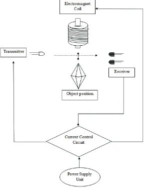
II. OVERVIEW
Magnetic materials are able to attract or repel each other apart or together with a force based on the magnetic field electromagnetic levitation block diagram how this system works.
405
The system can be understood in the following steps: i. Power supply unit provides the electrical power to
the CLCC.
ii. The CLCC controls the amount of current in the EM coil.
iii. EM coil acts as solenoid which exhibits magnetic properties at both end of it.
iv. The position of the object or load is near the coil. v. The CLCC adjusts the amount of the current based
on the feedback from the sensor that is placed just below the solenoid.
vi. The object or load suspends in the air once the correct position has been achieved.
III. LABPROJECT
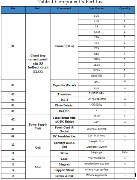
Initially, the instructor demonstrates the project to the students using the benchmark model. Each student is given the training kit including an instruction manual as the basic guideline to assemble the project. The part list to develop the magnetic levitation systems is shown in Table 1 [4]. Most of the components have already been included in the training kit except for the item no. 12, 14 and 15.
Table 1 Component’s Part List
Nevertheless the students are encouraged to transform the project into their own development by exploring alternative component and method as long as the main goal is reached. The lab project goal requires the students to
assemble the training kit which can levitate the load weigh around 10 gram in the air, with the minimum distance between the load and the solenoid is 1 cm [4, 5].
The power supply unit consists of two 12Vdc bridge transformer and one 15Vdc bridge transformer. The output from the transformer is supplied to the CLCC. The bridge transformer basically is a transformer that has a diode connected in bridge configuration to rectify the AC voltage from the 240V AC supply to 12V and 15 V respectively. In the meantime, since the current supply is high, a fan is desirable to be installed near the transformer for heat dissipation.
The CCLC with IR feedback circuit consists of voltage follower, differential amplifier, proportional plus derivative amplifier, emitter, photo-signal and photo reference. The circuit working principle is discussed further in the next section.
Solenoid coil is constructed using copper wires wrapped around a carriage bolt for 800 turns. The number of layers is estimated around 24 layers. There is a nylon flat washer on the bottom (the head end) and a common galvanized steel flat washer on the top. The coil length is twice the width of Scotch magic transparent tape, which secures the layers of windings [4]. Figure 2 shows the basic lifting image of solenoid.
Fig. 2 Basic Solenoid coil with carriage bolt act as the core.
This system is considered as a balanced system when the load is levitated. According to Newton’s first law of motion, if an object stays still, the sum of force on levitated point is zero or for this case, the gravitational force acted downward is cancelled out by the attraction force upward [6]. To prove this law, first the students need to calculate the force from the gravity where m is the mass of the load, 10 gram and a is the gravitational acceleration, 9.8m/s2.
406
To calculate the attraction force by the solenoid coil, the, Maxwell’s force formula in equation (3) is used [7].
ൌሺȗሻʹρͲȀሺʹʹሻ (3)
Where:
x ȝ0 = 4ʌ×10-7 N·Aí2
x F is the solenoid attraction force in Newton
x N is the number of turns of solenoid, 800 turns
x I is the current in the coil, 0.53Amp
x A is the surface area of attraction solenoid, 0.00005m2
x d is the length of the gap between the solenoid and a piece of metal, 0.025m
Therefore, substitute the value onto the formula gives:
The value of attraction force is almost the same as the gravitational force acting on the load.
IV. DESIGNOFCLCC IRFEEDBACKCIRCUIT This section explains how CLCC IR Feedback circuit operates. Figure 3 shows CLCC circuit develops by Hansen. B. [4] obtained during literature phases. The advantage of using infrared is to lesser noise produce by the ambient light.
Fig. 3 CCCL Magnetic Levitation Circuit diagram
The value of the bias resistor that is placed in series with an IR LED is depending on the IR LED rating. The value of current can be reduced linearly with the increase of the bias resistor based on Ohm’s Law shown in equation (4) where V is the supply voltage, 15V and R is 500ȍ, the bias resistor in series with the IR LED. For this case, 30mA current is yield, sufficient enough to light-up the IR LED.
(4)
For the photo-detector circuit measuring the position of the load, the value of the sensor resistor has to be large. This is because when the amount of light from the IR LED is reduced, the current generated from it will amplify the voltage that translates as the position of the load. For this case, 56Kȍ sensor resistor having a distance between the LED and the Photo-detector about 10cm yield the voltage of 4V. The student is encouraged to try different distance between the emitter and photo-detector to see the voltage difference during ON and OFF.
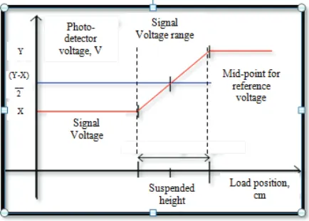
In order to determine the sensor resistor for the reference position of the load, the students have to measure operating range of photo-detector voltage. The mid-point of the operating voltage is the value of the reference voltage where to get the reference value, the potentiometer is used. For this case, the potentiometer value is 56Kȍ together with 10kȍ resistor which yield almost 7.5V as illustrated by the graph in Figure 4 [4].
Fig. 4 Graph photo-detector versus load position
407
The load sometimes can become unstable in a situation where the position of the load is above the reference point. During this period, the current is reduced to allow the load to displace lower. Unfortunately, the load may gain momentum during drop and eventually passes the reference position before the current flows in [4]. As we all know, the further the object from the source field, the lower the attraction force. Therefore, a compensator consists of a voltage divider couples with a capacitor to provide times for the current to increase when the load position reach the reference position. In this case, the compensator gives 0.1 second time delay before the current reduce.
The output amplifier amplifies the control signal to a higher value for switching transistor. The transistor basically allows the current to pass through it at ON state and completes the coil circuit. To avoid over current at transistor base, a 300ȍ is placed in series for protection. The value of the current at base is obtained by equation (5) where Vs is the supply voltage, 12V, Vb is the transistor
base voltage, 0.7V, Rb is the base resistor, 300ȍ and Ib is
the base current.
(5)
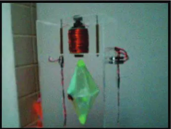
If the students follow all the guideline carefully, there should be no problem for them to demonstrate the magnetic levitation as shown in Figure 5.
Fig. 5 Demonstration of magnetic levitation
V. ASSESSMENT
It is estimated that the duration of this training kit project will be around 7-lab weeks. Since this project is proposed in electrical control system course, the students will have sufficient knowledge about the component and theory behind the magnetic levitation system.
It is essential that the mentoring is done properly in the lab. This task will not only to guide the student but also to give an opportunity for the instructor to evaluate the electrical assembly skill, soldering skill, troubleshooting skill and exhibit good safety practices throughout the whole
period of the project. The practical work assessment is vital in case the training kit project does not functional and is unable to troubleshoot. Component breakdown, unstable system and even damage PCB are some of the problems that might be anticipated to occur during assembly.
Besides that, to achieve the vision of the faculty in producing excellent communication skill graduates, it is crucial for the students to do a presentation of their project at the end of the course. Not only the practical part of the knowledge is assessed, other aspects like presentation and communication skills will be assessed too.
VI. CONCLUSION
As we entering year 2012, the challenges that we will be facing as educators in teaching technical courses have become increasingly difficult. The needs of graduates possess high technical skill is not an option anymore. The period of conventional way to teach the undergraduates about electrical control system has passed.
The proposal to include the magnetic levitation project along with theoretical lecture is a brilliant idea for the nation to move forward. It is important for the students to understand the control system - hands on and appreciate the technical information from it. We expect, the students to face difficult task in completing the project and hope that they can exhibit critical thinking skill to solve the problem. All the experiences and knowledge gained from here definitely will help the students upon graduation in getting a better job and performing well.
ACKNOWLEDGEMENT
The authors would like to acknowledge Universiti Teknikal Malaysia Melaka for supporting this work through a short term grant.
REFERENCE
[1]. H.H. Woodson and J.R. Melcher. Electromechanical Dynamics Part I. New York: Wiley, 1968. pp. 193– 200.
[2]. J.K. Roberge. Operational Amplifiers: Theory and Practice. New York: Wiley, 1975. pp. 214–217. [3]. Katie A. Lilienkamp and Kent Lundberg. Low-Cost
Magnetic Levitation Project Kits For Teaching Feedback System Design. American Control Conference, 2004.
[4]. Lance Williams. Electromagnetic Levitation Thesis, 2005. Lecture 19 MIT 8.02 Electricity and Magnetism, Spring 2002
[5]. Syahmi & Shafif Development of Electromagnetic Circuit Levitation, Final Year Report, 2010
408
[7]. Sir Isaac Newton, Philosophiæ Naturalis Principia Mathematica, 1687
[8]. James Clerk Maxwell, On Physical Lines of
Force. 1861 and 1862