Review
On the effect of geometrical designs and failure modes in composite axial
crushing: A literature review
Saijod T.W. Lau
a,⇑, M.R. Said
b, Mohd Yuhazri Yaakob
caFaculty of Engineering and Technology, Multimedia University, Jalan Ayer Keroh Lama, 75450 Melaka, Malaysia b
Faculty of Mechanical Engineering, Universiti Teknikal Malaysia Melaka, Locked Bag 1752, Pejabat Pos Durian Tunggal, 76109 Durian Tunggal, Melaka, Malaysia c
Faculty of Manufacturing Engineering, Universiti Teknikal Malaysia Melaka, Locked Bag 1752, Pejabat Pos Durian Tunggal, 76109 Durian Tunggal, Melaka, Malaysia
a r t i c l e
i n f o
Article history:
Available online 1 October 2011
Keywords: Fibres Buckling Axial crushing Numerical analysis
a b s t r a c t
Composite materials have been known for its low density, ease in fabrication, high structural rigidity, and wide range applications, i.e. aeronautic applications and automotive industry. Due to this, extensive stud-ies had been conducted to evaluate its axial crushing ability to replace metallic materials. In this paper, it reviewed the usage of fibre reinforced plastic composite (FRP) as an energy absorption application device. Failure modes and geometrical designs such as shapes, geometry and triggering effect have been studied where these factors affected on peak load and specific energy absorption significantly. Accordingly, numerical analysis for axial crushing of affected factors had been simulated to predict the failure mech-anisms of FRP composites.
Ó2011 Elsevier Ltd. All rights reserved.
Contents
1. Introduction . . . 803
2. Energy absorption in composite characterisation . . . 804
3. Factors affecting on peak load and energy absorption. . . 804
3.1. Failure mechanisms. . . 804
3.2. Shape and geometry . . . 805
3.3. Triggering. . . 808
3.4. Summary . . . 808
4. Simulation. . . 808
5. Application of axial crushing for safety purpose . . . 810
6. Conclusion . . . 811
References . . . 811
1. Introduction
In the past, thin wall metal tubes have been highly studied for its axial crushing ability[1,2]. Metal tubes subjected to axial crush-ing, energy was absorbed due to plastic deformation during the progressive fold formation[2]. In order to increase crashworthi-ness in term of unit mass volume energy absorption, some researchers had increased tube wall thickness [3,4]. Moreover, Cheng et al. had attempted with aluminium foam filled braided stainless steel tubes for better energy absorption [5]. However, these improvisations are no longer applicable especially for
passenger carrying application due to fuel consumption such as in aerospace, automotive industry and other weight concerning application. As a results, new materials like fibre reinforced plastic (FRP) have been extensively studied for their capabilities due to the fact that it is lighter and stronger[6,7]. Research groups reported that energy absorption of a well design FRP composite can perform better than metals[8–10]. Unlike metals, composite materials such as carbon and glass fibre reinforced plastics composites subjected to axial crushing will undergo of fracture to obtain energy absorp-tion rather than plastic deformaabsorp-tion which exhibited in metal tub-ing [11,12]. As reported [9], most energy absorption were contributed by failure modes of Mode I and Mode II fracture, energy absorbed during frond bending, and fibre fracture as well as friction at and within the crushed fronds[13].
0263-8223/$ - see front matterÓ2011 Elsevier Ltd. All rights reserved.
doi:10.1016/j.compstruct.2011.09.013
⇑ Corresponding author. Tel.: +60 6 252 3007; fax: +60 6 231 6552. E-mail addresses:[email protected],[email protected](S.T.W. Lau).
Contents lists available atSciVerse ScienceDirect
Composite Structures
In composite tubes fabrication, fibre orientations effects on axial crushing behaviour were studied. Carroll et al.[14]reported that for ±55° filament-wound glass fibre/epoxy under quasi-static com-pression, the failure depends on stress ratio and rate of loading. It was suggested that strength and stiffness were a function of loading direction and the total energy absorbed was related to the stress strain behaviour. On the other hand, epoxy/carbon fibre layers of (±0) and (±90) were able to crush progressively and absorbed more energy compared to layers (+45k/45k) which deformed plastically without fracture due to higher flexural rigidity[7].
In another experiment, studies on different materials stacking and the effect on crushing ability. Segmented composite tubes were investigated for their energy absorption under lateral and ax-ial compression. Abosbaia et al.[12,15] were using carbon, glass and cotton fabric to fabricate composite tube reinforced with epoxy by wet winding process. It was revealed that segmented composite tube performed better under axial loading compared to lateral crushing. In axial crushing, no significant improvement in segmented and non-segmented carbon/epoxy. However, it ab-sorbed highest energy amongst tested segmented FRP composites (i.e. glass and cotton/epoxy composite). Interestingly, segmented cotton–cotton–carbon/epoxy (CT–CT–C) FRP composite was en-hanced by 17% but segmented cotton–cotton–glass (CT–CT–GT) FRP decreased the energy absorption performance from the ones with cotton segmented (CT–CT–CT) FRP. On the other hand, Mahdi et al.[16] studied on the effect of using hybrid glass/carbon se-quence on energy absorption capability and revealed that Glass– Carbon–Glass (GCG) combination has the best energy absorption rather than GGC and CGG. The reason to this was glass fibre layers were failed under transverse and axial shear, while the carbon lay-ers were buckled. Unlike GGC and CGG segmented composites fail-ure occurred when the glass fibre layers debonded and carbon layer fractured.
Geometrical parameters aspect ratio was also used for studies in axial crushing. Mamalis et al.[13]investigated onL/w(length/ inner width) aspect ratio affected on axial crushing capability. He concluded that peak load (Pmax) decreases as aspect ratio of the compressed tube specimen becomes higher. Palanivelu et al.[17]
reported thatt/dort/w(wall thickness/outer diameter or width) aspect ratio of 0.045 for different shape influenced the crushing state i.e. square tube crushed catastrophically as compared to round tube both geometries crushed progressively However, both shapes were progressively crushed when aspect ratio of 0.083[18]. In this paper, many studies have been done in order to under-stand on the axial crushing capability of FRP composite. The objec-tive of this paper is to review failure modes and design factors such as shape, geometry, and triggers that affects on the peak load and total energy absorbed.
2. Energy absorption in composite characterisation
In axial crushing, tests are carried out by either quasi-static compression or impact loading. In static loading, a composite tube is compressed between two steel plates of a hydraulic press at low cross head speeds normally between the range of 1–10 mm/s. For impact loading dynamic test, it is carried out by using a drop ham-mer or an impactor. Accordingly, specimen dimensions were made based on the preliminary calculation to determine tube geometry in order to avoid buckling[13]. Tested tubes have typical length at 50–125 mm length, 20–100 mm outside diameter/width and 1–3 mm wall thickness. However, different shapes were applied for the test such as round, square, hexagon[17], cones[19], and plates[7].
Energy absorption capability is computed to determine its en-ergy dissipation rate for a crushing event. Enen-ergy absorption capa-bility on the total work done (WT) for composite crushing is equal to the area under the load–displacement curve and evaluated as
WT¼
Z
P ds; ð1Þ
wherePis the corresponding force on the structure ands is the cross head distance.
Energy absorption capability is also evaluated as per unit mass absorbed which commonly known as Specific Energy Absorption (SEA) and evaluated as
SEA¼WT
m ¼
WT
q
v
; ð2Þwheremis crushed mass,
q
is the composite material density, andv
is the volume of the crush specimen.3. Factors affecting on peak load and energy absorption
3.1. Failure mechanisms
Peak load is measured before material begin to fail under buck-ling such as local buckbuck-ling, global buckbuck-ling, yield (or fracture) or progressive crushing as shown inFig. 1 [20]. This buckling failure can further lead to either catastrophic or progressive failure as shown inFig. 2 [21]where the failure affected onto the load dis-placement curve. In the figure, the area under the curve represents the energy absorbed. When progressive failure happened, this area will be higher and constant load slightly occurred as crushing dis-placement increases.
Catastrophic failure will result in sudden drop of load thus low-er enlow-ergy absorbed. This happened due to specimen crushed was fractured in the mid-plane[22] or had longitudal cracks[17]as
shown inFig. 3a and b, respectively. On the other hand, progressive failure is the opposite of catastrophic failure where by more area under the curve can be observed. This result is due to multi-failure mode combinations (Mode I, Mode II, and Mode III) and local buck-ling were initiated during progressive crushing[23]and different energy absorption level was obtained. In Mode I and Mode II, splaying mode and sliding mode, respectively, gave higher energy absorption[24](c.f.Fig. 4) due to contribution of friction between laminates fibre and bending[7]. On top of that, fibre orientations played an important role in Mode I interlaminar fracture toughness which had been agreed with previous work [25]. In Mode III, energy absorption was lower as compared to Mode I and II. This was due to the mid-plane fracture and unstable collapse of the compressed tube [13]. However, this contradicts with another literature[23]that documented Mode III failure is due to matrix
deformation and fibre fracture that moved progressively through the elliptical structure (ellipticity ratio of 2.00). Moreover, it showed stable crushing failure along post crush stage and gave highest normalised specific energy absorption,ENS(explain in Sec-tion3.2), which is 22273.79 kJ/kg m2.
3.2. Shape and geometry
Many design shapes and structures had been made and its crushing behaviours were studied for their energy absorption capability.
On axial crushing for cross sectional shape, Palanivelu et al.[17]
reported that square and hexagonal shape witht/Dort/Waspect ratio of 0.045 crushed catastrophically but circular shape showed uniform and progressive crushing modes. Increasing the aspect Fig. 2.Lower energy absorption in catastrophic failure as compared to progressive failure[21].
ratio to 0.083, square and hexagonal shapes were crushed progres-sively. From the work, it is revealed that circular cross section with
t/Dratio of 0.083 was having the highest SEA of 30.4 kJ/kg com-pared to square and hexagonal cross section which recorded SEA of 12.3 kJ/kg and 16.4 kJ/kg, respectively. Abdewi et al.[26]tested on using radial corrugated cross section (RCCT) and circular cross section (CCT) composite tubes showed inFig. 5. The author con-cluded that corrugated tubes exhibited higher peak loads as well as specific energy absorption when compared to circular shape composite tubes. However, combination of radial corrugated sur-rounded by circular (RCSCT) composite tube failed to improve the load carrying capacity[27]as observed inFig. 6. In the figure, corrugated circular cross section exhibited higher peak load at longer displacement stroke compared to circular as well as combi-nation of that two cross sectional shapes. Furthermore, the area under the curve (represent SEA) of RCCT is larger than those two. Mahdi et al. studies on the effect of elliptical ratio on the nor-malised SEA,ENs, which the structure made of glass/epoxy compos-ite[23]. In the work,ENshas been modified where SEA equation was further divided by contacted cross-sectional area of the ellip-tical area. From the work, it is found that ellipticity ratio of 2.0 has higherENscompared to circular tubes and tubes with ellipticity
ratio of 1.5 and 1.75 shown inFig. 7. In the figure, as increasing ellipticity ratio, higherENscan be produced.
In geometrical studies, Mahdi et al.[28] investigated on the effect of conical shell angles onto the crushing capability. It is
reported that SEA of cylindrical structure absorbed better energy from conical shell which the Es value of 24 kJ/kg. Moreover in
Fig. 8, increasing cone vertex angle will decreased SEA, peak load (Pi) as well as volume reduction (VR) values. Alkateb et al.[29] re-ported that vertex angle in elliptical cone design was sensitive to crushing behaviour.Fig. 9showedENSand peak crush load-vertex
angle curves. From the figure, increasing vertex angle decreasing crushing load except for elliptical cone vertex angle of 12°.
How-ever forENs, one can see that it is increased exponentially with increasing the vertex angle.
Fig. 4.Splaying (Mode I) and sliding (Mode II) in axial crushing[9].
Fig. 5.Radial corrugated and circular shape[26].
Fig. 6.Load displacement curves of circular cross section (CCT), corrugated circular cross section (RCCT), and combination of the circular and corrugated circular cross section (RCSCT)[27].
0 5000 10000 15000 20000 25000
1 1.25 1.5 1.75 2 2.25
Ellipticity ratio
Normalised
SEA
(kJ/kg.m
2 )
Fig. 7.Normalised specific energy absorption against ellipticity ratio curve[23].
For other geometrical structure, Palanivelu et al. studied on hand lay-up glass fibre reinforced polyester composites namely on hourglass (HG) type A, B, X and Y, and conical circular (CC) type X and Y[17,18], c.f.Fig. 10. Form the work, the author reported that HG-A and HG-B exhibited higher SEA (21.1 kJ/kg and 22.5 kJ/kg, respectively) compared to HG-X and HG-Y which recorded 6.96 kJ/kg and 13.0 kJ/kg, respectively. Interestingly, from the
failure mechanisms point of view, HG-X and HG-Y did not fail cat-astrophically but it was due to the absence of circumferential delamination. Palanivelu et al. [17,18] reported conical circular geometry, CC-Y showed higher SEA compared to CC-X where the values of energy absorbed were 28.8 kJ/kg and 23.5 kJ/kg, respec-tively[17,18].
On the other hand, a study on cone–tube–cone composite struc-ture which the strucstruc-ture was similar to strucstruc-ture HG-A was inves-tigated[30]. In the study, Mahdi et al. reported that tubular part height influenced specific energy absorption where tubular height/total height ratio (normalised tubular height) between 0.06 and 0.11 showed high SEA, c.f.Fig. 11. From the figure, vertex angle of 10°gaveEsof 85.5 kJ/kg and it was higher about 18% than vertex angle of 15°. Another identical geometrical structure as
HG-B was also studied by Mahdi et al.[31]. In the reported work, cone–cone intersection composite with vertex angle of 20° and 25°absorbed more energy compared to 10°and 15°vertex angle. Comparing between two materials namely carbon fibre and glass fibre reinforced epoxy composites, it showed that material used (fibre as reinforcement) influence in energy absorbing capability due to the materials properties. However, both of the composite materials showed the similarity in trend where increased the 0
500 1000 1500 2000 2500 3000
0 6 12 18 24 30
Vertex angle (deg)
Normalised
SEA
(kJ/kg.m
2 )
0 10 20 30 40
Load (kN)
Fig. 9.ENSand peak crush load-vertex angle curves[29].
(c)
(d)
(a)
(b)
HG-X
HG-A
HG-B HG-Y
(e)
(f)
CC-X CC-Y
Fig. 10.Types of hourglass (HG) and conical circular structure tested[17].
vertex angle, SEA and crushing load increases (initial crushing load, ICL, and average crushing load, ACL) except for volume reduction (VR), c.f.Fig. 12.
Collectively, circular shape give a valuable comparison amongst all the shape tested. Furthermore, it can absorb most of the axial crushing energy compared to the other shapes except for radial corrugated circular ones. For geometrical studies, structure body parallel to the applied load gave the highest resistance in the event of crushing. Moreover increasing structure angle in any part of structure body for axial crushing affected to the SEA.
3.3. Triggering
Triggering is a process to form stress concentration on the edges of profile geometry to originate localised failure, thus this avoid the loads transfer to the whole structure. Therefore, triggering mecha-nisms on composites profile can prevent composite structures from crushing catastrophically. As described inFig. 2on the pro-gressive crushing curve, proper selection of triggering helps in con-tributing crush load to maximum level and the load can be maintained consistently as crushing displacement increases due to fracture mechanisms (i.e. splaying, fracture modes, etc.) took place. Accordingly, failed material during the crushing filled in the closed profile of the composite. As a result, crushing load in-creased which describe in the end of the figure.
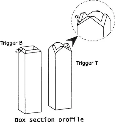
Jimenez et al.[21]reported that triggered composites profile lead to different energy absorbing capabilities. Composite box for type-B triggering shown inFig. 13(with
a
-angle of 30°and 60°)showed 25% different in specific energy absorption level. Peak load on the type-B composites (at 60°) showed highest loading at 74.7 kN. Comparing with box section, I section had 15% smaller capability. Furthermore peak load for I-beam composite has 60% smaller crush load. Investigation on triggering effect on different cross-sectional shapes was reported. Under quasi-static axial crushing, it is reported that peak load for edge triggering at 45°
was higher than 90°tulip triggering[18]. However, specific energy absorption for tulip triggering was higher than edge triggered for all cross section tubes tested. Palanivelu et al.[32]reported an in-crease of 7–9% in specific energy absorption for round shape with edge triggered compared to tulip type. However, square shape acted in opposite characteristics, instead. An increase of 16.5% of specific energy absorption was recorded for tulip type triggering. Carbon and glass for non-hybrid and hybrid of composite braided rod was fabricated and tested for its triggered effect on the energy absorption analysis[33]. It was concluded that conical triggered rod crushed progressively compared to non-tapered rod which lead to axial crack.
3.4. Summary
Table 1lists the geometrical, shape, and triggers affected on peak load and Specific Energy Absorption (SEA) for non-hybrid fi-bre reinforced plastics (FRPs) composites. Different materials lead to different energy absorption characteristics but same material with different shape/geometry resulted in different energy absorp-tion levels. With increasing thickness of the composite, peak load can increase by 2–3 folds as well as SEA by almost 2 folds. Accord-ingly, increasing in tube length yielded in different peak loads due to buckling effect[13]. On the other hand, triggering affect on peak load and SEA is significant.
4. Simulation
Mathematical simulation using numerical analysis has been carried out in order to predict composite behaviour for future applications. Often, these finite element simulation systems are
having three typical processing steps. Firstly, it is being building up the model which is creating up geometry structure, input of mechanical properties and other elements (e.g. boundary condi-tion). Secondly, non-linear dynamic analysis will be using to ana-lyse based on the parameter set. In this step, numerical process is taking place where calculation based on the parameters and con-straints assigned are running in the background. Finally will be the
Lo
post-processing analysis of results. Here, the results obtained will be the failure modes and failure patterns that will be observed and compared with the experimental data[34]. PAM-CRASH, LS-DYNA and ABAQUS [35], these non-linear finite element codes are widely used in design by industries and research institutes due to their ability to handle boundary condition parameters as tested materials collapses and other phenomena related to high deformation rate during crushing[36].
Anghileri et al. [36]compared numerical results with experi-mental test on composite tubes made of woven carbon fibre with two different stacking sequence, firstly is four layers of (0/90) and followed by another four layers of (45/45). In the work, ‘‘Bi-Phase’’ material model which allow the fibre and matrix of uni-directional plies to be given separate stiffness and strength proper-ties had been used. The author concluded that numerical results were within 3% from experimental test but more studied are re-quired for other geometries to be validated due to the number of parameters required in order to satisfy multi-objectives optimisa-tion. On the other hand, Mahdi et al. reported a simulations work
on corrugated composite tubes[37]. In the work, less constrains were configured (i.e. constraint completely at top section and fixed horizontal direction at the bottom part) and less parameters were focused (e.g. total compression, peak load, mean load, and energy absorbed). From the work, numerical results are quite consistent with the experimental ones where the error of the parameters tests less than 1%. However, comparing with metallic material is not applicable due to the different behaviour in material, i.e. cotton thermoplastic is having much lower strain than steel (brittle). Fur-thermore from the reported work [22], crushing behaviour of metallic materials (progressive crushing mode) is differed from fi-bre reinforced plastic (fracture crushing mode).
In other reported works [34,38], crushing on hybrid square sandwich FRP composite with corrugated and reinforced core were simulated. Although the reported simulation works out-come in both experimental and the simulation are almost same, the authors have made few assumptions on the modelling, i.e. manufacturing imperfections, modelled with-one-through thickness-thin shell element, and microscopic damage were not considered. Numerical analysis on ±45°braided pultrusion tubes[39], found that [0]4 lay-ers of pultruded tube were able to absorb highest energy amongst all tubes having the same thickness. Moreover, simulations at 6 m/ s and 14 m/s crushing speed concluded that the hybrid pultruded tubes were sensitive to tube length. However from the work, no experimental data were given to be verified.
Huang and Wang[40] established a two-layer finite element based on Chang-Chang failure criterion in LS-DYNA to simulate 14-ply T700/QY8911 (carbon fibre/BMI resin) subjected to quasi-static axial crushing. In the work, crushing triggers were intro-duced in the numerical simulations by using four-node quadrilat-eral Belytschko–Tsay shell element to initiate crushing process. From the work, post-evaluation of the photo from the experimen-tal and numerically showed good agreement but the numerical re-sults showed higher than the experimental ones (i.e. peak load and SEA).
Palanivelu et al.[35]reported on the simulating of circular and square cross section pultruded profile made of glass–polyester using two approaches namely, single layer and two layered shell elements with solid cohesive layer as triggering effect. The results revealed that both approaches lead to higher predicted peak load than the experimental ones. This happened due to the absence of delamination contributed to inaccurate results. McGregor et al.
[41,42] simulated on the comparison of using plug and without Fig. 13.Type of triggering effect that have been used[21].
Table 1
Non-hybrid FRP composites.
Materials Shape (mm,
outside dimensions)
Length (mm) Thickness (mm) Trigger Peak Load (kN) SEA (kJ/kg) Ref.
Carbon/epoxy h 100100 50.7 3.73 Flat surface 219 8.2 [10]
101.6 3.40 244 9.1
121.2 3.40 219 24.9
Glass/polyester h 2020 100 1 45°edge chamfered 2.22 – [15]
s Ø20 3.09 15.9
Glass/polyester h 4040 150 5 30°edge chamfered 61.4 38.0 [19]
Tulip 30° 66.7 39.0
Glass/polyester s Ø160 150 3.7 – 56.622 10.2 [24]
Carbon/epoxy s Ø100 110 3 – 156.00 29.00 [14]
plug initiator on square hollow section carbon fibre reinforced plastic composites. In the study, modelling stability was important in minimising between experimental and numerical results, i.e. chamfering modelling.
In summary, most of the published work related to simulation of energy absorption in composite axial crushing seems to have
focused on initiation of cracks due to triggering and progressive crushing failure modes. Moreover, the shape used for simulation mostly circular or square cross section due to ease in calculation and simulation on energy absorption.
5. Application of axial crushing for safety purpose
In the event of collision or blast, total energy absorbed by a material used is very crucial. Therefore, developed materials and design must be able to perform well for the safety of mankind, structures as well as other components on machine or equipment used.
An experiment[43]had been conducted on the axial crushing of tubes on agriculture aircraft seat shown inFig. 14a. In the figure, the crush tube was placed at an inclination angle to neutralise the moments between the weight of occupants, seat structures and the bending moment of the rail. A closed up of a steel collar that was used to fix at rail so that the tube will crush coaxially shows inFig. 14b. Using simple energy method, crashworthiness of the tubes parameter could be estimated for occupant survivabil-ity studies.
Barnet et al.[44]presented application of composite material in energy absorption capability in a certain military and civilian field. The author demonstrated that composite material was able to ab-sorb blast as good as metallic materials. On top of that, using com-posite material as car safety barrier simulated in LS-DYNA, showed that a car weight about 1000 kg able to stop after hitting composite barrier at speed of 80 km/h as compare to metallic material which the same car had overcame it.
In marine application[45], a study had been carried out on crushing of web girder in ship collision and grounding under in-plane loading. In ship grounding, primary bulkheads, deep frame and floors in bottom ship will suffer large in-plane forces. Mean-while, in collision, decks, side stringer stiffeners may also suffer torrential damage. The structural components mentioned are called as web girders. This is well presented inFig. 15 to show the different type of girders used. The authors[45] proposed a new theoretical model for crushing of web girders under localised in plane loads. By using plastically method of analysis (compressed two folds with second partly folding), existing methods were improvised whereby crushing factor plays a significant role in pre-dicting the mean crushing resistance.
Fig. 14.(a) Design model of agriculture aircraft seat for infantry and (b) closed up of crush tube to absorb blast energy[40].
6. Conclusion
Numerous experiments have been carried out to study FRP composites. Having advantageous of good lightweight energy absorption capability, FRP composites could be the next generation of metal substitution. Furthermore, improvisation on the energy absorption capability had been extensively studied. Accordingly, this paper summarises the recent researches on the factors that af-fected peak load and energy absorption capabilities.
In composite axial crushing, fracture failure contributed high energy absorption. Two types of fracture failure which had been categorised namely, catastrophic failure and progressive failure. Progressive failure absorbed more energy due to presence of mul-ti-failure modes which lead to different characteristics of energy absorption. Mode I and Mode II failure absorbed more energy due to friction between laminates and bending. However Mode III (mid-plane crushing), energy absorption was lower. Shapes and geometrical design factors in composite were studied. Shape such as square and circular with the samet/Wort/Daspect ratio showed different energy absorption levels. In axial crushing, 0.045 ratio of square cross section showed catastrophic crushing while circular cross section crushed progressively. Geometrical de-signs could improve energy absorption capability. Studies showed that hour glass shape would absorb less energy due to delamina-tion. In order to improve composite materials to crush progres-sively, triggering effect had been carried out. It is learnt that triggering affect on peak load, and SEA. Different type of triggers (edge chamfering and tulip trigger) lead to different energy absorp-tion capabilities. Studies on axial crushing had been extended to simulation and numerical analysis to predict their failure charac-teristics. However, this mode requires further improvisation due to assumptions made which, the composite material have equal volume fraction, and stress distributions are equal and so on but in real life these control parameters are difficulty to obtain.
After due research, effect of the manufacturing process onto the axial crushing should be study. From the past research, hand-lay up technique and filament winding have been concentrated and the axial crushing have been experimented. However, in the simulation works, one of the most assumptions made was imperfection of manufacturing. Therefore, new technique (i.e. resin transfer mould-ing, etc.) should be adopted in order to minimised the assumptions made during simulation. Hence, this will lead to a better result. On the other hand, using natural fibres (e.g. cotton, oil palm and coir) as reinforcement in plastic composite is potential study in the future due to the natural fibre are lower in density, environmental friendly, bio-degradable and most of all it is low in cost[46].
References
[1] Bardi FC, Yun HD, Kyriakides S. On the axisymmetric progressive crushing of circular tubes under axial compression. Int J Solids Struct 2003;40:3137–55. [2] DiPaolo BP, Tom JG. A study on an axial crush configuration response of thin
wall, steel box components: the quasi-static experiments. Int J Solids Struct 2006;43:7752–75.
[3] Santosa S, Wierzbicki T. Crash behaviour of box columns filled with aluminium honeycomb or foam. Compos Struct 1998;68(4):343–67.
[4] Santosa S, Wierzbicki T. Effect of an ultralight metal filler on the bending collapse behaviour of thin walled prismatic columns. Int J Mech Sci 1999;41(8):967–93.
[5] Cheng Q, Altenhof W, Jin SY, Powell C, Harte AM. Energy absorption of aluminium foam filled braided stainless steel tubes under quasi-static tensile loading conditions. Int J Mech Sci 2006;48:1223–33.
[6] Mamalis AG, Manolakos DE, Ioannidis MB, Papapostolou DP. The static and dynamic and axial collapse of CFRP square tubes: finite element modelling. Compos Struct 2006;74:213–25.
[7] Mamalis AG, Manolakos DE, Ioannidis MB, Papapostolou DP. On the experimental investigation of crack energy absorption in laminate splaying collapse mode of FRP tubular components. Compos Struct 2005;70:413–29.
[8] Ramakrishna S, Hamada H. Energy absorption characteristics of crash worthy structural composite materials. Key Eng Mater 1998;141–143(2):585–619.
[9] Savona CS, Hogg PJ. Effect of fracture toughness properties on the crushing of flat composite plates. Compos Sci Technol 2006;66:2317–28.
[10] Ramakrishna S. Microstructural design of composite materials for crashworthy structural applications. Mater Des 1997;18:167–73.
[11] Hull D. A unified approach to progressive crushing of fibre reinforced composite tubes. Compos Sci Technol 1993;35(3/4):231–46.
[12] Abosbaia AAS, Mahdi E, Hamouda AMS, Sahari BB. Quasi-static axial crushing of segmented and non segmented composite tubes. Compos Struct 2003;60:327–43.
[13] Mamalis AG, Manolakos DE, Ioannidis MB, Papapostolou DP. Crashworthy characteristics of axially statically compressed thin-walled square CFRP composite tubes: experimental. Compos Struct 2004;63:347–60.
[14] Carroll M, Ellyin F, Kujawski D, Chiu AS. The rate-dependent behaviour of ±55°
filament-wound glass–fibre/epoxy tubes under biaxial loading. Compos Sci Technol 1995;55:391–403.
[15] Abosbaia AAS, Mahdi E, Hamouda AMS, Sahari BB, Mokhtar AS. Energy absorption capability of laterally loaded segmented composite tubes. Compos Struct 2005;70:356–73.
[16] Mahdi E, Hamouda AMS, Sahari BB, Khalid YA. Effect of hybridisation on crushing behaviour of carbon/glass fibre circular-cylindrical shells. J Mater Proc Technol 2003;132:49–57.
[17] Palanivelu S, Paepegem W, Van Degrieck J, Kakogiannis D, Van Ackeren J, Van Hemelrijck D, et al. Comparative study of the quasi-static energy absorption of small-scale composite tubes with different geometrical shapes for use in sacrificial cladding structures. Polym Test 2010;29:381–96.
[18] Palanivelu S, Van Paepegem W, Degrieck J, Vantomme J, Kakogiannis D, Van Ackeren J, et al. Crushing and energy absorption performance of different geometrical shapes of small-scale glass/polyester composite tubes under quasi-static loading conditions. Compos Struct 2011;93:992–1007. [19] Mahdi E, Hamouda AMS, Sen AC. Quasi-static crushing of hybrid and
non-hybrid natural fibre composite solid cones. Compos Struct 2004;66:647–63. [20] Meidell A. Computer aided material selection for circular tubes designed to
resist axial crushing. Thin-Walled Struct 2009;47:962–9.
[21] Jimenez MA, Miravete A, Larrode E, Revuelta D. Effect of trigger geometry on energy absorption in composite profiles. Compos Struct 2000;48:107–11. [22] Bambach MR. Axial capacity and crushing of thin-walled metal, fibre–epoxy
and composite metal–fibre tubes. Thin-Walled Struct 2010;48:440–52. [23] Mahdi E, Homouda AMS, Mokhtar AS, Majid DL. Many aspects to improve
damage tolerance of collapsible composite energy absorber devices. Compos Struct 2005;67:175–87.
[24] Ghasemnejad H, Hadavinia H, Aboutorabi A. Effect of delamination failure in crashworthiness analysis of hybrid composite box structures. Mater Des 2010;31:1105–16.
[25] Hadavinia H, Ghasemnejad H. Effects of Mode-I and Mode-II interlaminar fracture toughness on the energy absorption of CFRP twill/weave composite box sections. Compos Struct 2009;89:303–14.
[26] Abdewi EF, Sulaiman S, Hamouda AMS, Mahdi E. Effect of geometry on the crushing behaviour of laminated corrugated composite tubes. J Mater Proc Technol 2006;172:394–9.
[27] Abdewi EF, Sulaiman S, Hamouda AMS, Mahdi E. Quasi-static axial and lateral crushing of radial corrugated composite tubes. Thin-Walled Struct 2008;46:320–32.
[28] Mahdi E, Hamouda AMS, Sahari BB, Khalid YA. Effect of residual stresses in filament wound laminated conical shell. J Mater Proc Technol 2003;138:291–6.
[29] Alkateb M, Mahdi E, Hamouda AMS, Hamdan MM. On the energy absorption capability of axially crushed composite elliptical cones. Compos Struct 2004;66:495–501.
[30] Mahdi E, Hamouda AMS, Sahari BB, Khalid YA. Experimental quasi static crushing of cone–tube–cone composite system. Compos Part: B 2003;34:285–302.
[31] Mahdi E, Sahari BB, Hamouda AMS, Khalid YA. An experimental investigation into crushing behaviour of filament-wound laminated cone–cone intersection composite shell. Compos Struct 2001;51:211–9.
[32] Palanivelu S, Van Paepegem W, Degrieck J, Van Ackeren J, Kakogiannis D, Van Hemelrijck D, et al. Experimental study on the axial crushing behaviour of pultruded composite tubes. Polym Test 2010;29:224–34.
[33] Saito H, Chirwa EC, Inai R, Hamada H. Energy absorption of braiding pultrusion process composite rods. Compos Struct 2002;55:407–17.
[34] Mamalis AG, Manolakos DE, Ioannidis MB, Kostazos PK, Papapostolou DP. Axial collapse of hybrid square sandwich composite tubular components with corrugated core: numerical modelling. Compos Struct 2002;58:571–82. [35] Palanivelu S, Van Paepegem W, Degrieck J, Kakogiannis D, Van Ackeren J, Van
Hemelrijck D, et al. Parametric study of crushing parameters and failure patterns of pultruded composite tubes using cohesive elements and seam, Part I: Central delamination and triggering modelling. Polym Test 2010;29:729–41. [36] Anghileri M, Chirwa EC, Lanzi L, Mentuccia F. An inverse approach to identify the constitutive model parameters for crash worthiness modelling of composite structures. Compos Struct 2005;68:65–74.
[37] Mahdi E, Mokhtar AS, Asari NA, Elfaki F, Abdullah EJ. Nonlinear finite analysis of axially crushed cotton fibre composite corrugated tubes. Compos Struct 2006;75:39–48.
[39] Han H, Taheri F, Pegg N, Lu U. A numerical study on the axial crushing response of hybrid pultruded and ±45°braided tubes. Compos Struct 2007;80:253–64. [40] Huang J, Wang X. Numerical and experimental investigation on the axial
crushing response of composite tubes. Compos Struct 2009;91:222–8. [41] McGregor CJ, Vaziri R, Poursartip A, Xinran X. Simulation of progressive
damage development in braided composite tubes under axial compression. Compos Part A 2007;38:2247–59.
[42] McGregor C, Vaziri R, Xiao X. Finite element modelling of the progressive crushing of braided composite tubes under axial impact. Int J Impact Eng 2010;37:662–72.
[43] Tabiei Ala, Nilakantan Gaurav. Axial crushing of tubes as an energy dissipating mechanism for the reduction of acceleration induced injuries from mine blast underneath infantry vehicles. Int J Impact Eng 2009;36:729–36.
[44] Barnat W, Dziewulski P, Niezgoda T, Panowicz R. Application of composites to impact energy absorption. Comput Mater Sci 2010. doi:10.1016/ j.commatsci.2010.05.03.
[45] Hong Lin, Amdahl Jorgen. Crushing resistance of web girders in ship collision and grounding. Mar Struct 2008;21:374–401.
![Fig. 1. Failure mode on axial compression: (1) global buckling, (2) local buckling, (3) fracture, and (4) progressive crushing [20].](https://thumb-ap.123doks.com/thumbv2/123dok/571987.67716/2.595.129.450.598.740/failure-compression-global-buckling-buckling-fracture-progressive-crushing.webp)
![Fig. 2. Lower energy absorption in catastrophic failure as compared to progressive failure [21].](https://thumb-ap.123doks.com/thumbv2/123dok/571987.67716/3.595.149.456.302.565/lower-energy-absorption-catastrophic-failure-compared-progressive-failure.webp)
![Fig. 4. Splaying (Mode I) and sliding (Mode II) in axial crushing [9].](https://thumb-ap.123doks.com/thumbv2/123dok/571987.67716/4.595.60.260.63.307/fig-splaying-mode-sliding-mode-ii-axial-crushing.webp)
![Fig. 9. ENS and peak crush load-vertex angle curves [29].](https://thumb-ap.123doks.com/thumbv2/123dok/571987.67716/5.595.141.465.487.740/fig-ens-peak-crush-load-vertex-angle-curves.webp)
![Fig. 12. Trend of both materials (a) CFRP and (b) GFRP. Initial crushing load (ICL),average crushing load (ACL), Specific Energy Absorption (SAE) and volumereduction (VR) [31].](https://thumb-ap.123doks.com/thumbv2/123dok/571987.67716/6.595.307.548.61.628/materials-initial-crushing-average-crushing-specic-absorption-volumereduction.webp)
![Fig. 15. Type of girders used in ship to resist crushing during collision and grounding [42].](https://thumb-ap.123doks.com/thumbv2/123dok/571987.67716/8.595.37.275.59.392/fig-type-girders-used-resist-crushing-collision-grounding.webp)