DOI: 10.12928/TELKOMNIKA.v14i1.2746 162
Active Disturbance Rejection Control of Thermal Power
Unit Coordinated System Based on Frequency Domain
Analysis
Ruiqing Zhang*1,Liangyu Ma2, Yongguang Ma2, Yang Liang1, Liwei Geng1
1
College of Mechanical and Electrical Engineering, Agricultural University of Hebei, Baoding 071001, Hebei, China
2
School of Control and Computer Engineering, North China Electric Power University, Baoding 071003, Hebei, China
*Corresponding author, email: [email protected]
Abstract
For the multi-input and multi-output, strong-coupling nonlinear features of coordinated system for thermal power unit, it is difficult for traditional PID coordinated control scheme to meet the power grid demand which often participates in peak regulation and frequency modulation. In this paper, inverse Nyquist array is employed to carry out frequency domain analysis of the plant model. Then Pseudo-diagonalization is used to design the static decoupling compensation matrix of the system. Above on these, the linear active disturbance rejection controller ofevery channel in coordinated system can be designed repectively. Dynamic coupling and system unknown parts are observed by extended state observerof ADRC and is compensated to thesystem in time. The simulation tests show that the disturbance rejection results of the load and the main steam pressure for the coordinated control system under LADRC is better than that of PID control.
Keywords: thermal powerunitcoordinated system, linear active disturbance rejection controller,
frequencydomain analysis, extended state observer, pseudodiagonalization
Copyright © 2016 Universitas Ahmad Dahlan. All rights reserved.
1. Introduction
With the increasing demandof power and increasingly close attention to environment people pay, large thermal power units have become the main units of power grid in China because of theirs high efficiency, low emission, load regulating sensitive and other advantages. Since the boiler in large thermal power unit often employs the once-through boiler unit without a drum, the transition process, where water is evaporated to steam, is instant, and this makes the dynamic parameters of once-through boiler unit, such as the unit load response quality, the main steam pressure, and other parameters, present stronger coupling and stronger nonlinear properties [1-5], and these make the unitmore difficult to be controlled. Therefore, in order to improve the unit load response speed and ensure the main steam pressure parameter more stable; in recent years it is becoming a hot research to master the basic characteristics of large-capacityt hermal power unit, and to research an advanced control strategy for the coordinated system of the unit [6-8].
controller [13], which use the unique ESO to estimate the disturbance of both internal uncertainties and external disturbances in system, and automatically compensates the total disturbance, thus for nonlinear, large inertia, uncertain time-delay complex systems, this method has better control quality [14-15]. But ADRC would be improved and perfected for complex industrial process applications, and especially the numerous parameters tuning problems in ADRC have become a fundamental problem to be solved in practical application. Since feedback control structure of Linear ADRC proposedby Professor Gao [16] employs linear form, and it not only makes the theoretical analysis of ADRC further development [17-19], but also its parameters tuning is greatly simplified, and easy to be used in practice. A large number of applied researches have shown that LADRC has a strong ability to control complex nonlinear uncertain objects.
Inthis paper, aiming 600MW supercritical once-through boiler unit, INA method is employed to carry on the system frequency domain analysis, pseudodiagonalization method is used to conduct the pre-compensation static decoupling design for the system, and the model unknown parts of the system and dynamic disturbances are observed by ESO of ADRC, and at the same time the observed value is compensated to the system in time. The simulation results show the effectiveness of the proposed control strategy.
2. Dynamic Charactertics of Object Model
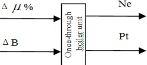
Coordinated system of the once-through boiler unit is a complicated large system. In general, the system can be seen as a three-input and three-output structure. Its input variables include the amount of fuel B, the main steam valve opening μ% and feed water W, and the corresponding output variables contain main steam pressure Pt, the real unit power Ne, and intermediate point’s enthalpy H. When the feed water of the system in accordance with certain coal-water ratio is adjusted, the system can be simplified to a two-input two-output system shown in Figure 1. Since there is a strong cross-coupling between the variables, the system also poses nonlinear and time-varying characteristics, and thus the stability margin of the system is reduced. It is difficult to achieve good control effect through using a single loop control.
Figure 1. The simplified inputs and outputs of the power unit
In this paper, the plant we discussed is a coordinated control system of the 600MW supercritical thermal power units in Henan province. Its turbine produced by Dongfang turbine factory with signal shaft, three cylinder four exhaust, double back-pressures, pure condensing steam turbine, uses a complex operation models with variable pressure; it has an intermediate reheat, and is in supercritical conditions. The boiler made by Dongfang boiler factory is a supercritical variable parameters facility. The rated power of units is 600MW, and the object pressure before the turbine is 24.1MPa.
The experimental platform is the Star-90 system developed by North China Electric Power University with the full scope simulation about all kinds of electric power units. Based on the Star-90 simulation system, the step response data can be acquired through matlab communicating program with the simulator, and the designing model of 600MW supercritical unit at 100% load is established with the improved genetic algorithm. The transfer functions of the coordinated system are following.
6.66 (49.3 1) 11
(56.7 1)(247.1 1) 123.5 1
s s
g
1.4293(272.5 1) 12(175.9 1)(126.3 1) 10 1
s g
s s s (2)
0.6073 21
(32.7 1) 141.5 1
g
s s (3)
0.7282(84.9 1) 22
(201.3 1)(94.66 1) 283.6 1
s g
s s s (4)
3. Frequency Domain Analysis of Coordinated System
As we all know, a precise mathematical model is required to the controlled object in the state space theory, the designed controller structure for multivariable system is quite complex, so that it is difficult to apply. In engineering, frequency domain analysis is a commonly methods of design and integration for control system. But coordinated system is a multiple-inputsand multiple-outputs coupling system,the Nyquist method often applied to analysis and optimized design a single variable, has no longer any meaning [11]. In this section, we use the inverse Nyquist array (INA) to conduct thefrequency domain analysis, and adopt pseudo diagonalization to develop a decoupling design for the above system.
3.1. Multivariable Control System Architecture and Frequency Domain Analysis
Stability is one of the most important indexes for control system design. For single-input single-output (SISO) system, the characteristic roots surrounded by (-1, j0) in a closed loop system can determine the distribution of its stability. But this method isnot suitable for multi-input and multi-output (MIMO) system, the stability identification of multivariable system is judged through the properties of return difference determinant of the system. Multivariable system diagram is shown in Figure 2.
Figure 2. Diagram of multivariable control system
Where, G(s) presents the controlled systems, Kcp(s) can be seen as a pre-compensator, Kc(s) is dynamic corrector, H(s) is called the feedback gain matrix, Q(s) represents the system forward channel matrix, then the transfer function matrix of the closed-loop system can be written as:
1( ) ( ) ( )
c
G I Q s H s Q s (5)
In which,
|D(s) |=|I+Q(s)H(s) | (6)
The above equation (6) is called the return difference determinant of the system.
The inverse Nyquist array method does not require the system completely decoupled, as long as the compensated system has diagonal dominance, which makes controller design become easy.
When the number of input variables is the same as the number of output in system, assumed the number of input variable as the q-th, at jω0 point, thus INA for the system transfer function matrix is expressed as a complex number.
0
(
)
, ,
1,
,
ik ik ik
g
j
j
i k
q
(7)For the values of m (m = 1, ..., q), we can obtain a matrix Am. In which,
, ∑ , , , 1, ⋯ , (8)
Eigenvalues and eigenvectors of the matrix Am are computed. The eigenvectors of the minimum eigenvalues constitute a column vector of km, and then through all of the m values; finally we obtain the smallest feature vectors, which constitute the compensation matrix Kcp.
Appling above the method, in the frequency ω = 0, we can get the precompensated array of Kcp for a boiler-turbine coordination system. Gershgorin band diagram of the system after compensated are carried out.
3.2. Diagonally Dominant Analysis of the Supercritical Unit Coordinated System
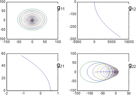
Diagonal dominance ofcoordination system about 600MW supercritical once-through boiler unit at 100% load is analyzed shown in Figure 3.
Figure 3. Diagonal dominance analysis of coordinated system about 600MW
From the above chart, we can seethat, g11 and g22in the system have surrounded the
origin, so that they are non-diagonal dominance and their variables have serious coupling, Decoupling networks would need to be developed in order to design their own controller.
Decoupling design of 600MW supercritical once-through boiler unit at 100% load is shown in Figure 4. The figure shows, Gershwin Goering circles of g11 and g22 all have no longer surroundedthe origin, the system hasalready a diagonal dominance, so the system has achieved a static decoupling, the decoupling matrix is Kcp = [-0.0116 -0.9999; -0.9951 0.0992].
From the above charts we can see that the open-loop transfer function matrix of boiler-turbine coordinated system has become diagonal dominance matrix, thus in the next section, we will develop two subsystemscontrollers by using ADRC respectively according to the design method of the single-loop controller.
-100 -50 0 50 100 -100
-50 0 50 100
-5000 0 5000 10000 -300
-200 -100 0
-2 -1 0 1
0 20 40 60
-150 -100 -50 0 50 -100
-50 0 50 100
g22
g21
g12
Figure 4. Precompensated decoupling design of coordinated system about 600MW
4. ADRC Design for Supercritical Unit Coordinated System
Coordinated system can be divided into two parts, turbine and boiler. Each part is a complex high-order nonlinear system, and it is very difficult to establish its accurate model. While ADRC does not demand to know the system model, we use the second order linear ADRC (LADRC) to design the turbine controller and the boiler controller.
4.1. The Structure of LADRC
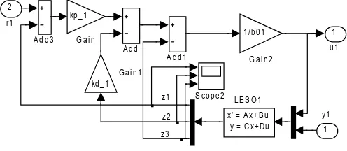
LADRC controller structure is shown in Figure 5.
Figure 5. LADRC controller structure
In general, when the controller is designed, the part which is higher than the third-order (including third-order) in the object can be seen as uncertain part of the dynamic system, so the system can be simplified as the following form:
0
( , ,
)
y
f y y w
b u
(9)
Where, u is the system input, y is the system output, w is the system unknown disturbance, f represents the system total disturbance, b0 is the controller gain, and the state equation of the system can be expressed as the following:
1 2
2 3 0
3
1
x x
x x b u
x h
y x
(10)
-1 0 1 2
-60 -40 -20 0 20
-6 -4 -2 0 2 -1
0 1 2 3
-0.80 -0.6 -0.4 -0.2 0 0.2
0.4 0.6 0.8
-100000 -5000 0 5000 100
200 300
z3 z2 z1
1 u 1
S co p e 2 x' = A x+ B u y = Cx+ Du L E S O 1
1 /b 0 1 G a i n 2 kd _ 1
G a i n 1 kp _ 1
G a i n A d d 3
A d d 1 A d d
2 r1
1 y1
g22
g21
Where x1, x2, x3 represents the system state variables,and h
LESO is the extended state observer of LADRC. The inputs of the observer include output u of the controller and output y of the system. The outputs of the observer are
z=[z1,z2,z3]
T
, where z3 is the expansion of the state, represents the system total disturbance,
which includes the system of external disturbances and uncertainty within the system disturbances.
Match the right observer gain, so that each observered valueof LESO can track each state of the system, i.e. → , → , → , , . z3 just dynamically estimates value f. The
coefficient matrix of the observer can be written respectively. 1 1 0
2 0 1
3 0 0 A , 0 1 0 2 0 3 B b ,
1 0 0
0 1 0
0 0 1 C , 0 0 0 0 0 0 D (11)
Assuming all the poles of the observer are arranged with ω0, the characteristic equation for LESO is following.
3 3 21 2 3 0
|
sI
A
|
s
s
s
s
(12)So we can obtain the following related equations,
2 3
1 3 0, 2 3 0 , 3 0
(13)
Where ω0 is called the observer bandwidth and it is the only need tuning parameters in LESO.
If the variable u is selected as the following,
0
0
( , , )
f y y w
u
u
b
(14)Then, the nonlinear system will become an integral series type system, namely.
y , , ̂ (15)
So we can use the "linear state error feedback (LSEF)" lawto design the ideal controller. State feedback control law can be designed the following.
(16)
Where, v is the set value.
Thus the closed-loop transfer function is described as following.
1( ) 2
p c
d p
k G s
s k s k
(17)
To simplify the parameters in the controller to be tuning, andωc is assumed as the bandwidth of the controller, so the characteristic polynomial of the controller represents as a function of ωc, i.e:
22
d p c
s
k s k
s
(18)4.2. The design of ADRC controller of Coordinated System
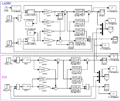
Based on pseudo diagonal decoupling compensation, adrc controller of above coordinated system is built in simulink of matlab environment.In order to compare the controlled result, PID controllerof the coordinated system is setcommonly. The two controllers about the controlled system are shown in Figure 6. In which, the adrc controller of the coordinated system are in the uper blue dotted box, and the PID controller of the plant is in the lower pink box.
Figure 6. The control system diagrams of LADRC and PID
4.3. ADRC Simulation Experiment for Coordinated System
For a 600MW supercritical unit coordinated system at 100% load, load disturbance and the main steam pressure disturbance experiments are carried out under LADRC and PID control respectively.
In which, ADRC controller parameters are:
01 1.89, 1 0.018, 01 0.00233
c b ,020.31,c2 0.029,b020.00019
PID controller parameters are:
10.625, 170.1
p i
K T ,Kp2 2.2751,Ti1 850
Figure 7. Comparisons of system step response curves under LADRC and PID
In Figure 7, loadstep disturbance experimentis conducted at 50s. The figure (a) is load response curve, and figure (b) is the main steam pressure response curve. The blue heavy line in the figures is under the control of LADRC response curve, the emerging green line is PID control under the response curve, and the red dashed line is the target of the system. The figures show that theplant is can be seen as a single variable after the pseudo diagonalization and decoupled by ADRC, and the effect of LADRC control is much better than the effect of the PID.
The comparisons of system step response curves for the main steam pressure disturbanceare shown in Figure 8.
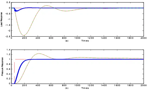
Figure 8. Main steam pressure step disturbance experiment
In Figure 8, the step disturbance experiment of the main steam pressure is conducted at 50s. The figure (a) is load response curve, and the figure (b) is the main steam pressure response curve. The blue heavy line in the figures is under the control of LADRC response curve, the emerging green line is PID control under the response curve, and the red dashed line is the target of the system. The figures show that the plant is can be seen as a single variable after the pseudo diagonalization and decoupled by ADRC, and the effect of LADRC control is much better than the effect of the PID.
As we can see from the figure 8, the respond index of loadandmain steam pressure with LADRCs is obviously superior to that ofPID.
5. Conclusion
In this paper, for coordinated system of a supercritical once-through boiler unit, frequency domain analysis is performed, steady compensation matrix is designed, and ADRC
0 200 400 600 800 1000 1200 1400 1600 1800 2000 0
0.5 1 1.5
0 200 400 600 800 1000 1200 1400 1600 1800 2000 0
0.1 0.2 0.3 0.4
0 2 0 0 4 0 0 6 0 0 8 0 0 1 0 0 0 1 2 0 0 1 4 0 0 1 6 0 0 1 8 0 0 2 0 0 0 -2 .5
-2 -1 .5 -1 -0 .5 0 0 . 5
(a ) Tim e s
Loa
d R
e
s
po
ns
e
0 2 0 0 4 0 0 6 0 0 8 0 0 1 0 0 0 1 2 0 0 1 4 0 0 1 6 0 0 1 8 0 0 2 0 0 0 0
0 . 2 0 . 4 0 . 6 0 . 8 1 1 . 2 1 . 4
(b ) Tim e s
P
res
s
ur
e
R
es
pon
s
control strategy of coordinated boiler-turbine system is established. Steady state decoupling and dynamic compensation control of the system are realized. Load step disturbance tests are carried out under PID control strategy and LADRCs control strategy respectively. The results show that the response curve controlled by LADRCsis significantly better than thatof the PID controller. This strategy combined the frequency domain analysis with disturbance rejection control technology to the coordinated system in thermal power units, is a new boiler-turbine coordination control scheme, and its controller can be designed quickly and efficiently, and has less tuning parameters, is easy to be applied in engineering.
Acknowledgements
This work was supported by NSF61174111.
References
[1] Zain Zaharn, Ruifeng Shi, Xiangjie Liu. The Power Unit Coordinated Control via Uniform Differential
Evolution Algorithm. TELKOMNIKA Indonesian Journal of Electrical Engineering. 2013; 11(7):
3498-3507.
[2] D Harikrishna, NV Srikanth. Dynamic Stability Enhancement of Power SystemsUsing Neural-Network
Controlled Static-Compensator. TELKOMNIKA Indonesian Journal of Electrical Engineering. 2012;
10(1): 9-16.
[3] Basler MJ, Schaefer RC. Understanding Power System Stability. IEEE Transactions on Industry
Applications. 2008; 44(2): 463-474.
[4] A RAY, HF Bowman. A Nonlinear Dynamic Model of a Once-Through Subcritical Steam Generator.
Transactions of the ASME. 1976; (9): 332-339.
[5] DeMello FP. Boiler models for system dynamic performance studies. IEEE Transactions on Power
Systems. 1991; 6(1): 66-74.
[6] Hossein Shahinzadeh, Sayed Mohsen Nasr-Azadani, Nazereh Jannesari. Applications of Particle Swarm Optimization Algorithm to Solving the Economic Load Dispatch of Units in Power Systems with Valve-Point Effects. International Journal of Electrical and Computer Engineering. 2014; 4(6): 858-867.
[7] Junjie Gu, Xiaowei Cao. Research on Control Method for Intermediate Point Temperature of
Supercritical Boiler Based on Active Disturbance Rejection Cascade Control. TELKOMNIKA
Indonesian Journal of Electrical Engineering. 2013; 11(7): 3957-3963.
[8] Han Zhongxu, et al. A new method of coordinated control system design and engineering application of super critical unit. Chinese Journal of mechanical engineering. 2009; 29(8): 75-81.
[9] Yongguang Ma, Ruiqing Zhang, Liangyu Ma, Bingshu Wang, et al. Active Disturbance Rejection
Control for Coordinated System of Supercritical Power Units. Journal of Applied Mathematics and
Statistics. 2013; 51(34): 112-120.
[10] Tan W, Liu JZ, Fang F, et al. Tuning of PID controllers forboiler-turbine units. ISA Transactions. 2004; 43(4): 571-583.
[11] Ma Ping, Tian Pei, Lv Lixia, et al. Application research of multivariable frequency domain method in thermal process control. Hebei electric power technology. 1994; (2): 75-78.
[12] Hawkins DJ. Pseudodiagonalisation and the in inverse Nyquist array method. Proceedings of IEEE
Part D. 1972; 119: 337-342.
[13] Han Jingqing. From PID to Active Disturbance Rejection Control. IEEE Transactions on Industrial
Electronics. 2009; 56(3): 900-906.
[14] Guan Zhimin, et al. Mainsteam temperature control of thermal power plant based on active disturbance rejection control. Journal of System Simulation. 2009; 21(1): 307-311.
[15] Huang Huanpao, et al. Auto disturbance rejection control scheme of coordinate system of thermal power unit. Chinese Journal of mechanical engineering. 2004; 24(10): 168-173.
[16] Zhiqiang Gao. Scaling and Bandwidth-Parameterization based Controller Tuning. Proceedings of
American controlconference. 2003: 4989-4996.
[17] Xue Wenchao, Huang Y. On performance analysis of ADRC for a class of MIMO lower-triangular nonlinearuncertain systems. ISATransactions. 2014; 53(4): 955-962.
[18] Zheng Qing, et al. A practical approach to disturbance decoupling control. Control Engineering
Practice. 2009; 17(9): 1016-1025.
[19] Brian Fast, et al. Active Disturbance Rejection Control of a MEMS Gyroscope.Procc. of 2008