DOI: 10.12928/TELKOMNIKA.v14i3A.4419 178
Bolt Fatigue Strength for the Tower of Large-scale
Horizontal Axis Wind Turbines
Pengwen Sun1*, Baiwei An1, Kai Long2
1
School of Mechanical Engineering, Inner Mongolia University of Technology, Hohhot, 010051, P. R. China
2
School of Renewable Energy, North China Electric Power University, Beijing, 102206, P. R. China *Corresponding author, e-mail: [email protected]
Abstract
For achieve the anti-fatigue strength design of the tower flange’s bolts for the large-scale horizontal axis wind turbines, the checking method of fatigue strength was proposed based on the Schmidt-Neuper model. According to the stiffness distribution ratio of single sector flange system, the nonlinear relationship of internal force-external tension was established for the bolt. The sequential stresses of the bolts were derived through the linear interpolation of load, and the fatigue cumulative damage distribution of the whole bolt circle was obtained by using the rain flow counting and accumulated damage calculation. Furthermore the position of the maximum fatigue cumulative damage can be found. And on this basis, the effect of some parameters such as retightening force of bolts, number of bolts and thickness of flange to the maximum fatigue cumulative damage was analyzed. The results showed that the proposed method and procedure was feasible and effective in analyzing and checking the fatigue strength of the tower flange bolts.
Keywords: fatigue strength, tower bolt, flange, Schmidt-Neuper model, wind turbine
Copyright © 2016 Universitas Ahmad Dahlan. All rights reserved.
1. Introduction
Bolted joint is one of the most common connection ways in wind turbine. With the development of large-scale wind turbine, the work environment is getting worse, and the design requirement is getting more and more critical correspondingly. They all make the fatigue cracks of joint bolts happen occasionally. In the research of bolt strength, Chen et al. calculated the wind turbine load based on blade element momentum theory and introduced a strength analysis method for hub and blade joint bolt [1]. He et al. has done the contact analysis of bolted joint part between hubs and blade bearing with the help of MCS Marc software [2]. Zhou et al. has tested the tensile strength of blade joint bolt using hydraulic material experimental equipment [3]. Liao et al. has proposed a numerical convergence principle of finite element method for the loading and unloading processes, and has realized the high accuracy calculation of joint bolt stress and load distribution. The prediction of joint bolt fatigue life based on damage mechanical analysis is also put forward [4, 5]. Minguez et al. has studied the influence of torque tightening method on joint bolt fatigue strength. Fatigue crack is one of the common crack ways of tower flange bolt [6]. According to it, Schmidy et al. has get the conclusion that geometric imperfections of certain shapes can greatly increase the value of stress amplitude, which can influence the fatigue life correspondingly [7].
is with fewer sectors for external load and bolt stress, and its calculation is relatively rougher comparing with Schmidt-Neuper algorithm, so Schmidt-Neuper algorithm is frequently used in engineering.
Aiming at solving the time series fatigue strength analysis problem for tower flange bolts of 2.0MW direct-driven wind turbine, the fatigue strength algorithm based on Schmidt-Neuper model is proposed in this paper. The cumulative damage distribution of flange bolts on the whole ring is calculated by rain flow counting and accumulated damage calculation. Furthermore the position of the maximum cumulative fatigue damage was found. The rule of influence of bolt preload, the number of bolts and the flange thickness on the maximum cumulative damage is considered as a research focal point.
2. Bolt Stress Calculation
The object of study in this paper is the joint bolts at the bottom of the tower for a 2.0MW direct-driven wind turbine, and the flange is the L type inner flange. The bolts are mainly effected by the tensile force, which is caused by the pre-load, bending moment etc., rather than shear load. In Schmidt-Neuper algorithm, the bending moment and the normal stress caused by compression impact on the tower’s wall. For any sector, the external tensile force occurs on the tower’s wall can be expressed by
n
Decompose the bending moment ܯ into its horizontal and vertical components ܯ௫ and
ܯ௬. Where is the intersection angle of the direction of positive x axis and any direction on the cross section of the tower.
The stiffness of bolt, flange and spacer can be expressed respectively by
b
In the Schmidt-Neuper algorithm, the bolted joint is regarded as the spring-like interconnection. The flange and spacer are considered as series connection, and their composite equivalent stiffness can be expressed by
S
The flange spacer and the bolt can be considered as parallel connection, and their composite equivalent stiffness is
E
B
C
C
The stiffness proportions of the components are
Where ݇ is the stiffness proportion of the bolt; ݆ is the stiffness proportion of the set of spacer and flange.
Where ܽ is the minimum distance between the bolt’s center position and the inner diameter of flange, and ܾ is the minimum distance between the bolt’s center position and the center position of tower’s thin wall.
Suppose the preload of the bolt is ܨ௬. Based on Schmidt-Neuper algorithm, the piecewise equation is
The relation between the bolt internal force ܨ and the external tensile force ܼ can be depicted into the following piecewise expression
The stress of the bolt cross section is expressed by
s
3.1. Design and Technical Parameters
the specific fatigue strength over 2×10⁶ times of strikes is pointed out in the standard S-N curve.
The detail category (DC) is also defined in the curve. For example, DC=36. It means the fatigue strength represented by stress is 36MPs, when the stress has circulated over 2×10⁶ times. For
the bolts with diameter larger than 30mm, DC damping parameter with the consideration of bolt’s size can be expressed by
0.25s
30
k
d
(11)Where
d
is the pitch diameter of the bolt (mm)Figure 1. S-N curve for weld material
Apparently, the value of DC has a great impact on the material’s fatigue strength. The value of DC is decided by the factor of bolt’s technology, which can refer to the Section 5.3.3.5 of standard GL2010. The reference values of DC are given in Table 1, where Fsmax is the
maximum internal force of the bolt under limit load; 0.2min
F is the internal force when the bolt is
with 0.2% elastic strain. In [11], the standards VDI2230, Eurcode3 and their bolt fatigue experimental data are compared, where DC is set to 36 under conservative design principle.
Table 1. Value of detail categories
DC Description 50 Rolling, heat treatment
Hot galvanizing surface treatment 71 or
) 85 , 2
71 min(
min 2 . 0
max
F
FS Rolling, hear treatment
The choice of safety factors of the components and materials are also conservative, which are shown in Table 2.
Table 2. Value of safety factors
Value Standard
Material safety factor 1.10 IEC 61400 Component safety factor 1.15 GL2010
3.2. Numerical Analysis Result
strength of material is 10.9 grade, which means the yield strength is 900MPa. The inside and outside diameters of the spacer are 40.4mm and 72mm respectively. The thickness of spacer is 6mm. The inside and outside diameters of the flange are 2785 mm and 3145 mm respectively. The diameter of the bolt’s central line is 2965 m and the thickness of flange is 70 mm. The bolt preload is applied with 70% of the material’s yield strength, i.e. 614.88kN. The design life of the bolt is 20 years. It means the bolt can bear 1×10⁷ times of strike. According to the algorithm in Section 1, the nonlinear relation between the external tensile force and the bolt stress can be depicted in Figure 2.
Figure 2. Non-linear relationship between tensile force and bolt stress
According to GL2010 standard [9], the loads at the center of flange cross section under 70 kinds of operating conditions can be calculated by Focus software. The time series external tensile force Z can be computed from formula (1). To obtain the cumulative damage distribution for all the bolts in the whole ring, the fatigue damage is calculated every 15°. Based on the nonlinear relation in Figure 2, the values of time series stresses are first obtained using linear interpolation, then the cumulative damage of bolts is calculated based on rain flow counting and Minzer method. The bolt cumulative damage distribution respect to different angles is shown in Figure 3 [10, 11].
Figure 3. Distribution of the fatigue damage
and the value of the cumulative damage is 0.555, which satisfy the design requirement of fatigue strength.
Figure 4. Distribution of the fatigue damage
4. Results and Analysis
4.1. The Influence of Preload on Fatigue Strength
To study the influence of bolt preload on maximum cumulative damage, different preloads are loaded according to different proportion of maximum preload bolt can bear. In this research the proportion of preload force increased by 5% from 50% to 90% and only the maximum cumulative damage is considered. The maximum cumulative damages for different bolt preloads are listed in Table 3.
Table 3. Fatigue analysis results with different preload of bolts
Preload Proportion %
Preload Value/kN
Minimum Stress/MPa
Maximum Stress/MP
Maximum cumulative damage
50 439.20 426.91 473.05 2.048
55 483.12 471.91 518.05 1.556
60 527.04 516.91 563.71 1.011
65 570.96 554.91 615.42 0.556
70 614.88 599.91 660.76 0.555
75 658.80 644.91 705.32 0.501
80 702.72 689.91 750.05 0.486
85 746.64 734.91 795.71 0.432
90 790.56 784.91 845.71 0.432
To illustrate the results, the stress value for curve with different preload of bolts are shown in Table 4.
Table 4. Stress value for curve with different preload of bolts
Preload Proportion/% -z2 stress/MPa -z1stress/MPa z1stress/MPa z2 stress/MPa
50 321.72 415.64 429.18 548.10
55 369.75 473.45 543.32 656.89
60 410.53 506.12 555.01 697.18
65 419.70 547.10 622.90 750.30
70 435.68 589.10 645.30 789.20
75 484.30 631.30 718.70 865.70
80 516.60 673.30 766.70 923.40
85 548.80 715.40 814.60 981.20
In Table 4, the maximum cumulative damage is decreased with increasing preload of bolt. This means that the fatigue strength of bolt is improved when the preload is increased suitably. When the value of bolt’s preload is relatively larger, e.g. the preload is 90% of the strength bolt can withstand, the maximum stress is larger. Considering the requirement of yield strength and safety factor of material, design of bolt preload should be limited by the maximum strength. In Table 3, the proportions of the preloads are 85% and 90% of the value of maximum cumulative damage. This is because the maximum time series stress is in the range of values corresponding to
Z
1. In those two situations, the curves of nonlinear relation between tensile force and bolt stress, as shown in Figure 2, are parallel. Since the range of stress isn’t changed, the value of fatigue damage keeps same. When the value of bolt’s preload is too small, the range of the bolt’s time series maximum stress is expanded, and even exceeds the range of stress values corresponding to
Z
1. It leads to the increasing of fatigue damage. In the industry, a regular loosening detection of bolt has a great significance.4.2. The Influence of Number of Bolts on Fatigue Strength
To study the influence of different numbers of bolts on the maximum cumulative damage, the systems with different numbers of bolts are researched. In this research bolts are increased with 20, and only the maximum cumulative damage is considered. The maximum cumulative damages with different numbers of bolts are listed in Table 5.
Table 5. Fatigue analysis results with different number of bolts
Bolt number
Minimum stress/MPa
Maximum stress/MPa
Maximum Cumulative damage
Fatigue Safety Coefficient
95 541.30 641.64 0.694 1.44
105 586.64 654.54 0.356 2.81
115 591.03 656.38 0.298 3.36
125 599.86 657.23 0.158 6.33
135 601.04 669.01 0.109 9.17
145 606.47 674.55 0.099 10.11
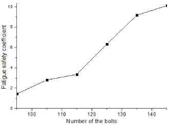
From Table 5, we can know that the range of bolt stress extremum values is shrunk with the increasing of bolt’s number, and the maximum cumulative damage is also reduced correspondingly. The reciprocal of maximum cumulative damage is defined as fatigue safety coefficient, so the relation between the bolt’s number and safety coefficient can be described in Figure 5.
Figure 5. Curve of fatigue safety coefficient with the number of bolts
values corresponding to
Z
1. The cumulative damage is increased, and it will lead to the rapid decreasing of fatigue safety coefficient.4.3. The Influence of Thickness of Flange on Fatigue Strength
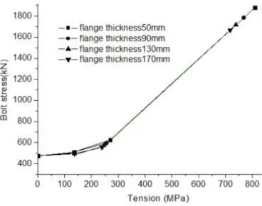
The influences of thickness of flange on fatigue strength are in two aspects. One aspect is proportion of bolt load; the other aspect is the nonlinear relationship between bolt load and external tensile force. The nonlinear relationship with different thickness of flange is shown in Figure 6. When the thickness of flange is increased, inflection point z1 changes little, inflection point z2 goes down.
Figure 6. Non-linear relationship between tensile force and bolt stress
To study the influence of thickness of flange on maximum cumulative damage, different thicknesses of flange are considered. In this research the thickness of flange is increased by 20mm from 50mm to 170mm and only the maximum cumulative damage is considered. The fatigue analysis results with different flange thickness are shown in Table 6.
Table 6. Fatigue analysis results with different flange thickness
Flange thickness/mm Proportion p Proportion q Maximum Cumulative damage
50 0.2422 0.7578 0.834
70 0.2203 0.7797 0.555
90 0.2012 0.7988 0.372
110 0.1844 0.8156 0.196
130 0.1697 0.8303 0.169
150 0.1566 0.8434 0.115
170 0.1451 0.8549 0.068
Because the influences of thickness of flange on fatigue strength are in two aspects, the relationship between maximum cumulative damage and thickness of flange is nonlinear. From Table 6, with decreasing thickness of flange, proportion k is increasing and maximum cumulative damage is also increasing. The thickness of flange does not only influence the fatigue strength of bolt, but also influence the limit and fatigue strength of the flange itself. This paper only discusses the influence of thickness of flange on fatigue strength of bolt.
5. Conclusion
the bolts were obtained. The distribution of the cumulative damage of bolts on the whole ring was calculated based on rain flow counting and accumulated damage calculation. Furthermore the position of the maximum fatigue cumulative damage was found. The effect of some parameters such as bolt preload, number of bolts and flange thickness to the maximum fatigue cumulative damage was analyzed. The results showed that the method and procedure presented in the paper was feasible and effective in the fatigue strength analysis for tower bolts.
Acknowledgements
This work is supported by the Inner Mongolia Natural Science Foundation of China in 2014 (NO. 2014MS0514).
References
[1] Chen Y, Tian P, Liu X, et al. Research on strength calculation methods of rotor hub of HAWTs. Acta Energiae Solaris Sinica. 2010; 31(7): 912-916.
[2] Ananth DVN, Kumar VN. Flux Based Sensorless Speed Sensing and Real and Reactive Power Flow Control with Look-up Table based Maximum Power Point Tracking Technique for Grid Connected Doubly Fed Induction Generator. Indonesian Journal of Electrical Engineering and Informatics. 2015; 3(4): 239-260.
[3] Zou GP, Zhang C, Cao Y, et al. Tension test and strength calculation on holding bolt of wind turbine blade. Journal of Liaoning Technical University. 2010; 29(6): 1110-1112.
[4] Liao RD, Sun YJ, Zhang WZ. Nonlinear Analysis of Axial-load and stress distribution for threaded connection. Chinese Journal of Mechanical Engineering. 2009; 22(6): 869-875.
[5] Liao RD, Sun YJ, Zhang WZ. Applicability of damage models for failure analysis of thread bolts. Engineering Fracture Mechanics. 2011; 78(3): 514-524.
[6] Ganesh C, Anupama S, Kumar MBH. Control of Wind Energy Conversion System and Power Quality Improvement in the Sub Rated Region Using Extremum Seeking. Indonesian Journal of Electrical Engineering and Informatics. 2016; 4(1): 14-23.
[7] MN Khoshrodi, M Jannati, T Sutikno. A Review of Wind Speed Estimation for Wind Turbine Systems Based on Kalman Filter Technique. International Journal of Electrical and Computer Engineering (IJECE). 2016; 6 (4); 1406-1411.
[8] De NS, Leoncini X. Critical behavior of the XY-rotor model on regular and small-world networks. Physical Review E Statistical Nonlinear & Soft Matter Physics. 2013; 88(1-1): 2252-2279.
[9] Gies H, Sánchezguillén J, Vázquez R A. Quantum effective actions from nonperturbative worldline dynamics. Journal of High Energy Physics. 2005; 2005(8): 824-829.
[10] Zare A, Foroozantabar A. Adaptive Robust Control of Variable Speed Wind Turbine Generator. Bulletin of Electrical Engineering and Informatics. 2015; 4(3): 196-203.