ISSN: 1693-6930
accredited by DGHE (DIKTI), Decree No: 51/Dikti/Kep/2010 505
Water Inrush Characteristics with Roadway Excavation
Approaching to Fault
Shuren Wang1, Hu Wang2
1,2School of Civil Engineering and Mechanics, Yanshan University, Qinhuangdao, China
e-mail: [email protected], [email protected]
Abstrak
Bencana lonjakan air merupakan faktor penting dalam keamanan produksi tambang batubara. Pengambil jalan dalam lapisan tanah didalam Tambang Batubara Danhou telah dilakukan dengan latar belakang teknik sesuai dengan hubungan spasial dari jalan, lapisan kedap air, kondisi cacat dan kondisi pembebanan, aktivasi model cacat mekanik di bawah gangguan penggalian jalan raya saat dibangun, kondisi aktivasi cacat, kriteria kriteria lonjakan aliran air masuk, dan lonjakan aliran air tiga mode. Sebuah model tiga dimensi untuk perhitungan numerik dibangun dengan menggunakan FLAC3D. Melalui perhitungan kopling fluida-padat, kerusakan batuan sekitarnya dan kegagalannya, lonjakan pembentukan kanal air, dan proses evolusi lonjakan aliran air dari penggalian jalan yang mendekati kesalahan telah dianalisis, sebagai tambahan, bidang perpindahan, medan tegangan dan karakteristik kegagalan plastik batuan sekitarnya karakteristik jalan raya itu telah pula diungkap. Selanjutnya, di bawah kondisi tekanan air yang berbeda, ketebalan batuan kedap air, perpindahan kesalahan, dan sudut kemiringan kesalahan, mode jalan lonjakan aliran air dan karakteristik evolusinya telah dianalisis secara komperatif dalam tulisan ini.
Kata kunci: jalan, kesalahan, kopling fluida-padat, lonjakan aliran air
Abstract
Water inrush disaster is an important factor in restricting safe production of the coal mine. Taking the roadway in seam in Danhou Coal Mine, as the engineering background, according to the spatial relationship of the roadway, the impermeable layer, the fault and the loading conditions, the fault activation mechanical model under the roadway excavation disturbance was built, and the fault activation conditions, roadway water inrush criterion and water inrush three modes were put forward. A three-dimensional numerical calculation models were built by using FLAC3D. Through fluid-solid coupling calculation, the surrounding rock damage and failure, the water inrush channel formation, and the evolution process of water inrush of the roadway excavation approaching the fault were analyzed. Moreover, the displacement field, the stress field and the surrounding rock plastic failure characteristics of the roadway were revealed. Furthermore, under the conditions of different water pressure, impermeable rock thickness, fault displacement, and fault dip angles, the roadway water inrush modes and their evolution characteristics were comparatively analyzed.
Keywords: fault, fluid-solid coupling, roadway, water inrush
1. Introduction
Confined water in the Ordovician limestone is one of the hidden troubles that threaten safe production of mines in north China, which is characterized by high water pressure, and large amount water. With the continuous increase of the depth, the mining is subject to different Ordovician threat of flooding. Especially in the case of fault structures development, mining disturbance has the potential to fault activation, and due to aquifer conducting the mining face can cause water inrush. In case of water inrush, the mine normal production will be affected, and the workers' lives will get endangered by such a disaster, which even lead to the mine closedown [1].
failure depth under different mine pressure with Rock Failure Process Analysis (RFPA). Q.H. Zhu et. Al [5] studied the water inrush process of the mining floor under the combined effect of the mining stress and the confined water pressure. S.X. Yin [6] put forward the water inrush mode of the seam floor, and did the water inrush mechanism analysis according to the different geological conditions. J. Han et. Al [7] analyzed the water inrush mechanism of the mining face near the fault. H.L. Liu et. Al [8] completed the simulation analysis of the whole water inrush process from the seam floor under the mining disturbance with RFPA. S. Wildemeersch et. Al [9] performed an uncertainty analysis based on both the hydraulic head and water discharge rate observation using the Hybrid Finite Element Mixing Cell (HFEMC) method. Q. Wu et. Al [10] identified the most dangerous time occurring possible lagging water-inrush to a coal mine based on the variable parameter rheology-seepage coupling model. K. Li et. Al [11] analyzed the fault activation law of the mining floor based on a practical water inrush example. J.H. Tang et. Al [12] obtained the expression of critical water pressure for the collapse pillar water inrush using the thick plate theory of elastic mechanics, and so on.
Although various researches have been conducted on the water inrush mechanism in coal mines, the roadway water inrush modes and their evolution process have been rarely reported by far [13-14]. Therefore, concerning the roadway excavation in seam in Danhou Coal Mine, it is one of great importance to analyze the water inrush modes and their evolution characteristics of the roadway excavation.
2. Enginering Situation
Danhou Coal Mine is located in Yuxian County, Zhangjiakou City, Hebei Province, China. Its annual production capacity designed is 1.50 Mt/a. The No. 3 mining area is located in the Yuxian basin, with complex hydrogeological conditions, and the normal production of the mining area is seriously constrained by Ordovician limestone aquifer.
The hydrogeological type of No. 3 mining area is a complex karst water-filled deposit, which is a mainly floor water inrush from the Ordovician limestone aquifer. The Ordovician limestone aquifer is located in the seam floor, with fully recharge, well permeability, large water gushing and rapid recovery the water level, and the complexity conditions. The hydrostatic pressure of the confined aquifer is usually 2.00-4.12 MPa. Between the seam and the Ordovician limestone, a layer of impermeable mudstone is better developed. However, the deposition thickness of this layer changes from the seam as 0.47-35.43 m.
There are developed faults in No. 3 mining area, mainly are normal faults. The total number of these faults is 19, all of which are cut deep to the limestone and may conduct the Ordovician limestone aquifer on condition that mining construction expose these faults.
3. Fault Activation Conditions and Water Inrush Modes 3.1. Fault Activation Mechanical Model
The fault activation is that the fault plane produces plastic failure and come into a hydraulic conductivity state from the non-hydraulic conductivity state.
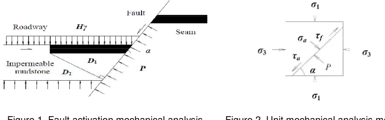
Assuming that a normal fault is located in front of the coal roadway, with the dip angle α, the loading over the roadway can be simplified a uniformly distributed stress Hγ, where H is the tunnel depth, γ is the average density of the rock on the roadway. The fault activation mechanical analysis model is shown in Figure 1.
Assuming the footwall and the hanging wall on both sides of the fault are elastic material. Under the mining disturbance stress and the confined aquifer water pressure, when the shear force of the fault plane is greater than the maximum shear capacity of the fault material, the fault plane can shear slip and come into the plastic failure state. So the fault can be regarded as being activated.
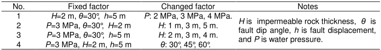
3.2. Fault Activation Mechanics Analysis
plane of the unit will produce the shear stress τf to resist being activated. Assuming the confined Assuming that the strength of the unit material obeys the Mohr-Coulomb yield criterion, the shear stress τfto resist being activated is written as Equation (3).
ϕ
σ
τ
f =c+ atan(3) Then the fault activation condition is τa≥τf. When the fault is in the critical activation state, combining Equation (1), Equation (2) and Equation (3), Equation (4) can be obtained as follows: stress σ3 have the following relationships with the tunnel depth H.
σ1=Hγ (5)
σ3=Kσ3=KHγ (6)
Where K, is the lateral pressure coefficient.
If the critical water pressure value of the roadway floor as the fault being activated is Pc, then Equation (7) can be obtained from Equation (4).
ϕ
Equation (7) is the expression of the critical water pressure as the fault being activated.
3.3. Roadway Water Inrush Mode Analysis
After the fault is activated, the confined water level can rise above the hanging wall along the fault failure plane. With the roadway excavation approaching to the fault, the plastic failure depth of the roadway floor will increase and the front seam protection thickness will decrease synchronously. Then, according to the spatial location and the chronological order, there are three modes of water inrush: inrush from the floor, inrush from the working face, and inrush from both the floor and the working face.
As shown in Figure 1, α isthe fault dip angle. Assuming that D1 and D2 arethe minimum horizontal distance and the minimum normal distance from the roadway working face to the fault respectively. On the other hand, assuming that the seam effective strength within D1 is S1, and the impermeable rock effective strength within D2 is S2, then if the water inrush from the floor and the working face occur together during the roadway excavation, the following equation can be obtained.
According to equation (1), Equation (9) can be expressed as follows:
α
So the critical angle αc of the fault can be obtained from Equation (9).
2
S
>
, the water inrush is from the roadway working face and conversely, and when thefault dip angle α<αc,
S
1D
1<
S
2D
2, the water inrush is from the roadway floor.4. The Computational Model and Simulation Analysis Programs 4.1. Building the Calculation Model
On the basis of the roadway water inrushes in Danhou Coal Mine, the tunnel surrounding rock and the fault spatial location, the roadway excavation engineering geological model and three-dimension numerical simulation model were built. As shown in Figure 3, the model consists of sandstone, seam, mudstone and Ordovician limestone aquifer. The calculation conditions in Figure 3 are as follows: the fault dip angle is 30°, the fault displacement is 5.0 m, the impermeable layer thickness of the roadway floor is 2.0 m. The computational model was 55.36 m long, 20 m wide, and 40 m high in the x-, y-, and z-axis. The roadway excavation dimension was 4.6 m wide and 4.0 m high. The model was divided into 57496 zones and 61709 grid-points.
4.2. Boundary Conditions and Water Inrush Criteria
The model was restricted horizontal movement on four sides with its bottom fixed and its top free. The destruction of rock material was assumed to obey the Mohr-Coulomb strength criterion. A uniformly distributed load 6.0 MPa was applied on the model top to simulate the weight load on the roadway.
The model was surrounded by impermeable boundary on four sides, but the permeable boundary was assumed on the model top and on its bottom. A confined water pressure was fixed at the model bottom.
The fault was simulated with a contact plane element, the hanging wall and the footwall could slip along the fault plane. According to field investigation, exploration data, indoor and outdoor test results, the physical mechanics parameters and the hydrodynamics parameters of the rocks were listed in Table 1 and Table 2 respectively.
Sandstone; Coal; Mudstone; Ordovician limestone aquifer; Roadway
Figure 3. Computational model and its meshes
Table 1. The physical mechanics parameters
First, considering the confined water influence, the initial stress field balance calculation of the model was conducted, and after that, the displacement field and the velocity field are cleared.
Second, the excavation process of the roadway was simulated step by step, and the initial excavation length of the roadway at each step was 5.0 m. In order to reveal the water inrush evolution characteristics, when the roadway was near the fault, the excavation length of the roadway at each step reduced to 1.0 m.
Finally, under the conditions of different water pressure, impermeable rock thickness, fault displacement, and fault dip angles, the roadway water inrush modes and their evolution characteristics were comparatively analyzed. The comparative analysis programs were listed in Table 3.
Table 3. A variety of simulation analysis programs
No. Fixed factor Changed factor Notes
1 H=2 m, θ=30°, h=5 m P: 2 MPa, 3 MPa, 4 MPa.
5.1. Water Inrush Characteristics during the Roadway Excavation
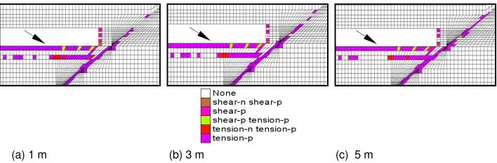
For simulation program No. 1, when the confined water pressure acting on the roadway floor was 3.0 MPa, the plastic failure of the surrounding rock of the roadway was shown in Figure 4. When the step-by-step roadway excavation approaches to the fault along the seam floor, the roadway water inrush occurred.
As shown in Figure 4(a), when the horizontal distance from the roadway working face to the fault was about 4.0 m, there were increasing plastic failure in the roadway floor and the top of the impermeable rock near the fault under the mining disturbance stress and the confined aquifer water pressure. Nevertheless, had the fault been activated, the water inrush did not appear since the water inrush failure channel had not been formed.
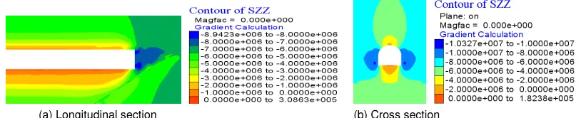
As shown in Figure 5(a), when the roadway floor water inrush occurred, the maximum displacement emerged in the floor near the fault like a beam bending deformation. Meanwhile, there emerged the convex displacement field to the free face in the roadway. Overall, it can be seen from Figure 5(b), the displacement in the floor was obviously larger than other positions.
(a)Before water inrush (b) After water inrush (c) Cross section after water inrush
Figure 4. Plastic failure elements in the surrounding rocks
(a) Longitudinal section (b) Cross section
Figure 5. Vertical displacement field in the surrounding rocks
As shown in Figure 6, with the excavation progress, both displacements of the roof and the floor in the roadway showed an increasing tendency, and near the water inrush position the displacement curves became flat. With the increasing pressure of the confined water, the displacement increasing rate in the floor was more significant than in the roadway roof. The reasons for this phenomenon were mainly that the normal distance from the roadway floor to the fault was getting smaller and smaller, and the fault was easy to slip and rebound, which resulted in significant displacements in the roadway floor. On the other hand, since the roof was less affected by the confined water, the roof sinking displacement was mainly due to the strain energy releasing of the surrounding rock during the roadway excavation.
Figure 6. Vertical displacement curves during the roadway excavation
(a) Longitudinal section (b) Cross section
Figure 7. Vertical principal stress field of roadway excavation. -3
-2 -1 0 1 2 3 4 5 6 7 8
1 2 3 4 5
Excavation steps
D
is
p
la
c
e
m
e
n
t
[m
m
]
As shown in Figure 7, there emerged a wide range of tensile stress in the floor and much larger compressive stress concentration areas in the front of the working face. All these mechanical effects were consistent with the displacement field shown in Figure 5.
5.2. Water Inrush Characteristics of Different Water Pressure Conditions
Simulation program No. 1: As shown in Figure 8, with the confined water pressure gradually increasing, the plastic failure elements and the damage extent increased in the impermeable rock. At the same time, the plastic failure elements and the damage extent in the plane also showed an increasing tendency. These results indicate the further activation of the fault hydraulic conductivity. Moreover, the water inrush mode had a gradual transition, i.e. inrush from the working face (or bottom) to mainly from the floor, which could cause the water inrush more serious and earlier.
5.3. Water Inrush Characteristics of Different Fault Displacements
Simulation program No. 2: As shown in Figure 9, with the increase of the fault displacement, the plastic failure areas gradually reduced in the impermeable layer, but the plastic failure along the fault plane increased a bit, which indicated that the roadway had some lag of water inrush and water inrush became more difficult.
5.4. Water Inrush Characteristics of Different Impermeable Rock Thickness
Simulation program No. 3: As shown in Figure 10, with the increase of the thickness of the impermeable rock, the plastic failure areas obviously reduced in the impermeable layer, but the plastic failure elements along the fault plane almost remained the same, the water inrush mode had a gradual transition, the inrush from the floor to that mainly from the working face (or bottom). When the impermeable layer thickness exceeded 3.0 m, it was little influence to water inrush. So, there was a critical value of the impermeable layer thickness to induce water inrush during the roadway excavation.
(a) 2 MPa (b) 3 MPa (c) 4 MPa
Figure 8. Plastic failure elements under different water pressures
(a) 1 m (b) 3 m (c) 5 m
(a) 2 m (b) 3 m (c) 4 m
Figure 10. Plastic failure elements under different impermeable rock thickness
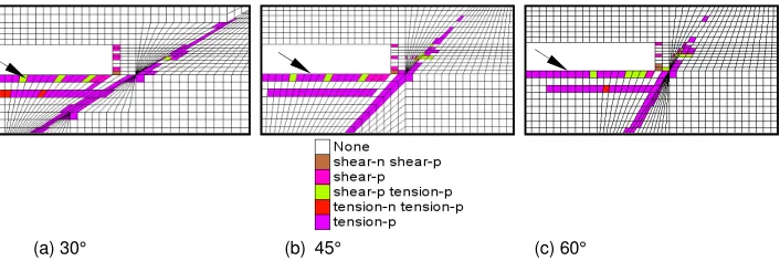
(a) 30° (b) 45° (c) 60°
Figure 11. Plastic failure elements under different fault dip angles
5.5. Water Inrush Characteristics of Different Fault Dip Angles
Simulation program No. 4: As shown in Figure 11, with the enlargement of the fault dip angles, the plastic failure areas gradually reduced in the impermeable layer and the fault plane, the fault activation became more difficult. The water inrush mode had a gradual transition, the inrush from the floor to that mainly from the working face (or bottom). Therefore, the large angle fault could postpone the water inrush time relatively.
In the process of the roadway excavation, the smaller dip angle fault was prone to water inrush, because the smaller dip angle fault reduced the impermeable rock thickness to a large extent, on the other hand, the smaller dip angle fault could be easily activated. Therefore, a wider waterproof coal pillar should be set when encountering a smaller dip angle fault during the roadway excavation.
6. Conclusion
Under the mining disturbance stress and the confined aquifer water pressure, when the shear force of the fault plane is greater than the maximum shear capacity of the fault material, the fault can be activated. Roadway water inrush must meet two conditions: (a) the fault is activated; (b) the fractured channel of water inrush is formed.
According to the spatial location and the chronological order, there are three modes of water inrush: inrush from the floor, inrush from the working face, and inrush from both the floor and the working face.
Under the conditions of different water pressure, impermeable rock thickness, fault displacement, and fault dip angles, the roadway water inrush modes and their evolution characteristics are obviously different. The results are reference and guidance to design safety coal pillars and roadway safe excavation.
Acknowledgments
References
[1] Wu Q, Zhang ZL, Ma JF. A new practical methodology of the coal floor water bursting evaluating Ⅰ
-The master controlling index system construction. Journal of China Coal Society. 2007; 32(1): 42-47. [2] Hu YQ, Zhao YS, Yang D. 3D solid-liquid coupling experiment study into deformation destruction of
coal stope. Journal of Liaoning Technical University. 2007; 26(4): 520-523.
[3] Kong HL, Miao XX, Wang LZ, Zhang Y, Chen ZQ, Hang Y, Chen ZQ. Analysis of the harmfulness of water-inrush from coal seam floor based on seepage instability theory. Journal of China University of Mining and Technology. 2007; 17(4): 453-458.
[4] Liu Y. Numerical analysis of breaking depth of coal floor caused by mining pressure. Journal of Xi’an University of Science and Technology. 2008; 28(1):11-14.
[5] Zhu QH, Feng MM, Mao XB. Numerical analysis of water inrush from working-face floor during mining. Journal of China University of Mining and Technology. 2008; 18(2): 159-163.
[6] Yin SX. Modes and mechanism for water inrushes from coal seam floor. Journal of Xi’an University of Science and Technology. 2009; 29(6): 661-665.
[7] Han J, Shi LQ, Yu XG, Wei JC. Mechanism of mine water-inrush through a fault from the floor. Mining Science and Technology (China). 2009; 19(3): 276-281.
[8] Liu HL, Yang TH, Yu QL, Chen SK, Wei CH. Numerical analysis on the process of water inrush from the floor of seam 12 in Fangezhuang coal mine. Coal Geology & Exploration. 2010; 38(3): 27-31. [9] Wildemeersch S, Brouyère S, Orban Ph, Couturier J, Dingelstadt C, Veschkens M, Dassargues A.
Application of the Hybrid Finite Element Mixing Cell method to an abandoned coalfield in Belgium.
Journal of Hydrology. 2010; 392, (3-4): 188-200.
[10] Wu Q, Zhu B, Shou SQ. Flow-solid coupling simulation method analysis and time independent of lagging water-inrush near mine fault belt. Chinese Journal of Rock Mechanics and Engineering. 2011; 30(1): 93-104.
[11] Li K, Mao XB, Chen L, Zhang LY. Research on fault activation and risk analysis of water inrush in mining floor above confined aquifer. Chinese Quarterly of Mechanics. 2011; 32(2): 261-268.
[12] Tang JH, Bai HB, Yao BH, Wu Y. Theoretical analysis on water-inrush mechanism of concealed collapse pillars in floor. Mining Science and Technology (China). 2011; 21(1): 57-60.
[13] Rajab A, Umar K, Hamdani D, Aminuddin S, Suwarno, Abe Y, Tsuchie M, Kozako M, Ohtsuka S, Hikita M. Partial discharge phase distribution of palm oil as insulating liquid. TELKOMNIKA. 2011; 9(1): 151-160.