Abstract— An underwater glider is a type of an unmanned underwater vehicle (UUV). The movement of an underwater glider in the water is based on the buoyancy-propelled for float and fixed-winged for stabilizing the glider’s body. However, a fixed wing underwater glider has limitation to avoid hitting the obstacle in front of it. To overcome this problem, the application of fin system in underwater glider is needed. In this project, a methodology was introduced which is design a flexible fin system of an underwater glider for obstacle avoidance purpose. This final year project mainly focused on SolidWorks’s simulation and analysis of -30°, -45°, -60° for submerge and rise up at 30°, 45°, 60° to get the most suitable angle for the glider’s fin system to submerge and rise up. The UTeM underwater glider is modified from fixed to flexible wing. Hence, Peripheral Interface Controller (PIC) is used to program the movement of the glider’s wings for upward at 45°and downward at -45°in the water. Thus, a flexible fin system for obstacle avoidance is designed and applied in UTeM underwater glider.
Index Terms—Underwater glider, fin system, obstacle avoidance.
I. INTRODUCTION
Malaysia is situated in the strategic position in the region of Southeast Asia and Singapore, South China Sea and Sulu Sea. Malacca Strait is concluding as a narrow and a shallow water area with average 53km depths where south of strait has average 40km depth shallower than northern, average depth about 66km [1]. There are many of the maritime activities are available along the strait. This strait seeks adequate protection to avoid piracy and influences due to the highest priorities of marine resource defend and protection [2-7].
However, there also has a lot of plastic that float in the sea. Plastic manufactured from many chemicals which impact on human or animals. The plastic will cover camera lens operation. This is a challenge for underwater glider activity, because glider cannot identify the trajectory of movement if the sensor and the camera was covered by a plastic [8 – 10]. Hence, the obstacle will cause accidents and make the glider damage.
This project proposed is to design the obstacle avoidance for unmanned underwater vehicle using fin system. The advantages of this project are to enhance the system of underwater glider nowadays become more effective in terms of speed, upward and downward glides.
Manuscript received August, 2013.
Mohd Shahrieel Mohd Aras, Faculty of Electrical Engineering, Universiti Teknikal Malaysia Melaka, Ayer Keroh, Melaka, Malaysia.
M.F. Basar, Faculty of Engineering Technology, Universiti Teknikal Malaysia Melaka, Ayer Keroh, Melaka, Malaysia.
Dr. Shahrum Shah Abdullah, Faculty of Electrical Engineering, Universiti Teknologi Malaysia, Johor, Malaysia.
Fadilah Binti Abdul Azis, Faculty of Electrical Engineering, Universiti Teknikal Malaysia Melaka, Ayer Keroh, Melaka, Malaysia.
Fara Ashikin Binti Ali, Faculty of Electrical Engineering, Universiti Teknikal Malaysia Melaka, Ayer Keroh, Melaka, Malaysia.
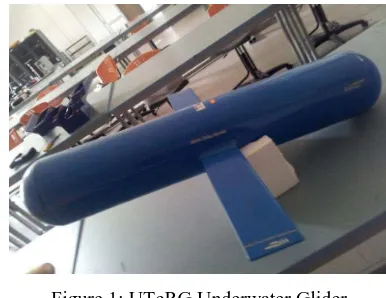
Based on the literature review, there is some methodology has been used to fix the obstacle avoidance of underwater glider’s problems. The enhancement of this project is to develop a flexible fin system in UTeM Glider for obstacle avoidance. The previous UTeM Glider with fixed fin as shown in Fig. 1. The details of the design and development of underwater Glider can refer to [11].
Figure 1: UTeRG Underwater Glider
These underwater robots need an obstacle avoidance system to identify the obstacle and avoid from damage. The underwater ballast tank system is used in previous UTeM Glider to deep diving. Hence, the movement speed of the fixed wing glider is slow. The gilder takes more time to submerge manually when facing obstacles. Fixed wing system is difficult to fully avoid the obstacle. So, a flexible fin system is needed to overcome this problem. Before apply the flexible fin system, the angle of glider’s submerge and rise up need to consider for the best result in term of buoyancy, pressure and speed effects.
II.METHODOLOGY
This project started with defining and identifies the current problem situation that related to this project. This helped in getting understood an overall picture of the project. Design parts are divided into hardware and software part. This includes experiments, designs and simulation repeated to fulfill of the requirement needed. This project started with the title proposal stage. In this part, the whole project overview is explained to provide a general view on this project. In literature review research, there are numerous journals, forum, paper and others need lots of review. The analysis and testing stage are conducted in order to fill all requirements. Finally, a report is presented based on the analysis and result of all of the experiments. Fig. 2 shows the overall design that has been done in this project. There are three main categories which are software, hardware and electronic circuit design. The closed loop system of obstacle avoidance system used in an underwater glider. PIC microcontroller used as the controller of the whole system. The fin system was driven by
Obstacle Avoidance System for Unmanned
Underwater Vehicle Using Fin System
the PIC controller. The sensor is used to determine the error of wings between desired input and actual output.
Figure 2: Fin System Design
A.Fin System
Fish has a fin based propulsion and perfect nervous system to consist of both of high speed cruising ingenious responses [12]. The main purpose of fin system is for the movement of underwater glider obstacle avoidance. Fish can be divided into two types which one is median and paired. Median fins are single, vertical fins are the back and underside of the fish. While, paired fins are identical to each side of the fish body. Current researches are mostly fin structure, neural control in fish and fish motion which important for the future to help engineers and scientists attempting Biomimicry of maneuverable fin-based locomotion in shallow surge zones [13-16].
Computing the fluid dynamics occurred when oscillating pectoral fins of fish during fish swimming. The functions of the fin area for swimming, stability, and steering.
Furthermore, each fin had its own characteristic have own task as follows:
i. The dorsal and fins save the level in the water and keep in from rolling.
ii. The caudal fins consist movement the fish forward and steer.
iii.The pelvic fins help to keep the fish level in the water and balance.
iv.The pectoral fins help the fish steer and brake.
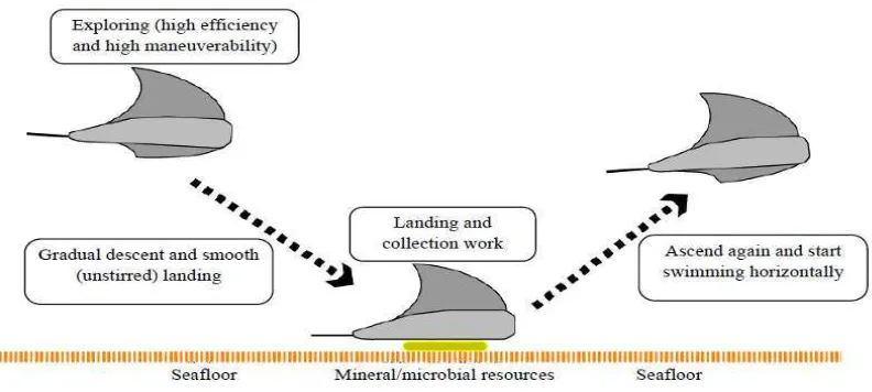
Figure 3: The appearance of the developed underwater vehicle (swimming in the water) [17]
In Mechatronic technology, a flexible oscillating fin propulsion system was built to realize flexible movement of fish [17]. Furthermore, advanced autonomous control logic was developed to create a lifelike swimming fish robot capable of 3D autonomous moving without cables. Fig. 3 shows the appearance of the developed underwater vehicle (swimming in the water). In Fig. 4 shows the concept of fish movements for prototype of the flat fish robot. This is aimed at building an underwater vehicle with flexible oscillating wings that can move smoothly based on “the principle of wing flapping.
Figure 4: Concept of flat fish robot [15]
B.Hardware Implementation
The hardware implementation is one of the parts of this project. SK40C board, servo motor driver, sensor and power supply are the main component in this hardware implementation. Fig. 5 shows the design of UTeM’s glider
i. 2cm - 400cm non-contact measurement function, ii. Ranging accuracy can reach to 3mm
iii.The modules include ultrasonic transmitters, receiver and control circuit.
Figure 5: UTeRG Underwater Glider uses the Solidworks software
Ultrasonic ranging module HC-SR04 sensor is working at DC 5V with 5mA current. The maximum range to detect the obstacle us 4m and the minimum range is 2cm. It also can measure the obstacle 0-15 angle [15]. It will connect to the SK40C board and give the signal when the obstacle occurs and the coding will control the motor of wing for obstacle avoidance purpose.
C.Mechanical Construction Design
Mechanical part is the most significant in developing fin system of underwater glider. Lots of elements need to be considered during designing the underwater glider such as size, stability, material, and buoyancy. The underwater glider designed in a hydrodynamic shape to reduce friction when moving in the water. This glider is made from fiberglass because it has a high degree of design flexibility, affordable, versatile, strength and durability, non-conductive and the most important thing is that it non-corrosive. The underwater glider designed with an estimated volume (106cm x 90cm x 20cm wide) as Fig. 6 shows the design of flexible wing of UTeM glider. These wings are used the sealing condition of servo motor at the hole beside the glider.
Silicone glue was the use for seal the hole to avoid water leakage happen to the pressure hull of UTeM glider in order to control the glider for rise up and submerge into the water. In this project, water proof servo motor, Traxxas 2056 used to control the movement of the wing. The features of this motor are 86 Oz-in torque and transit Time 0.23 Sec/60°. Traxxas 2056 High-Torque Waterproof Servo is high quality products from the vendor and it is built to meet the standard of IP67 waterproof [15]. It also has rust and corrosion protection while being sealed protected.
Figure 6: Flexible Wing UTeM Glider
The software implementation consists of drawing and C language programming. For both activities are completing this project, SolidWorks, PIC C Compiler CCS, Proteus and Express PCB software are used to accomplish the software implementation. In this project, PIC C Compiler CCS is used to type the coding. Besides that, it also used to simulate the coding before upload to the PIC16F877A [18-19]. Fig. 7 shows the electronic wing controller interfaced used in this project.
Figure 7: Electronic wing controller interfaced.
III. RESULT AND DISCUSSION
This experiment is based on the simulation result of flow trajectories in SolidWorks simulation. The general setting in this simulation as shown in Table 1.
Table 1: Parameter of Simulation on Solidworks
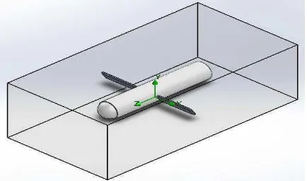
The medium of water is used in this simulation because the glider is used in the water and the density of water is 1000 kg/ . The velocity of the glider is 0.13 m/s by referring in paper [16]. The movement of the glider is set at x, y and z-axis because this simulation is wanted to choose the angle that suitable to rise up and submerge. Fig. 8 shows the computational of x, y and z-axis of the area of this simulations flow trajectory will be run.
A.Suitable Wing’s Angle for Submerge
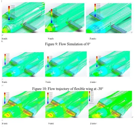
Fig. 9 shows that the flow trajectory of the glider when the angle is 0°or flat with the body of the glider. The result shows that the upper pressure and low pressure on both of the wings are same. Same pressure at the upside and downside of wings make glider can move forward without changing at z-axis, y-axis and z-axis position, ignore any disturbance.
Comparison of -30°, -45° and -60° for submerge is shown in Figure 12, 13 and 14 by using reference axis at x-axis, y-axis and z-axis. The less differ flow pressure compare to 3 references axis can be ignored and focus on z-axis. In Fig. 10, pressure applied at the front of the wing is a bit higher than pressure at the back of the wings. The higher pressure will make the wing turning down and therefore make the glider going down when the glider is moving forward at 0.1279 m/s. The speed for turning the glider down might slowly because the difference of pressure on the upside and downside wing are small.
Fig. 11 shows that the pressure applied at the front of the wing is larger than the back of each wing. This will cause the glider submerge easily due to the differences of pressure. According to Le-Chateliers’s principle, increasing the
pressure of the system at equilibrium will shift the equilibrium in the direction in which the pressure is reduced. Based on this principle, the higher pressure at the front of the wing will cause the wing to move. However, the wing is fixed at servo motor and this force will make the glider to submerge as in hypothesis.
The difference of pressure at the front and the back of the wing in Fig. 12 is smaller than -30°and -45°. Conceptually, it can hard drive the glider to downward. The glider might stop move forward because the forward speed of the glider is slow, 0.1279 m/s. Thus, based on simulation that has been made, -45 degree° is the most suitable angle for the glider to submerge.
B.Wing’s angle for Rise
Fig. 13 shows larger differ of pressure compare to other angle. It can make the glider rise up smoothly with the help of buoyancy force acted by the surrounding water. The wing keeps it positive 45° because the Pulse-width Modulation (PWM) controlled by PIC coding. The upward force at the wing will transfer to the glider and make the glider rise up.
Figure 9: Flow Simulation of 0°
Figure 10: Flow trajectory of flexible wing at -30°
Figure 12: Flow trajectory of flexible wing at -60°
Figure 13: Flow trajectory of flexible wing at 45°
Table 2 shows the result of drag force and lift force from simulation. The minimum drag force is suitable for submerge and rise up. And, the highest lift force is the best angle for rise up and submerges. From the result of submerge condition, lift force differs less compare each other. So, drag force need to consider and become the first factor to choose the suitable angle.
Table 2: Result of different angle yields force on fin.
The minimum of drag force of the angle is -0.2738N. A negative value is show direction of flow trajectory and do not mean the value of force. Then, the rise up angle is comparison between 45°and 60°because highest lift of force. But, -43, 45°is most suitable because the minimum of drag force. Hence, -45°is suitable for submerge and 45°for rise up.
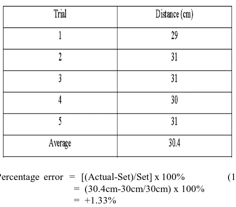
The experimental set up where the distance between the obstacle and ultrasonic sensor are fixed to 30 cm based on coding. Once the sensor sense the box, the glider’s wing will move. Table 3 shows the result of 5 trials that has been done to get the average distance. From the result, the distance that ultrasonic sensor can sense the obstacle is in the range of 29cm to 31 cm. The average range is 30.4cm. The range of sensor set in the coding of PIC is 30cm, so the percentage of error as equation 1 as below:
Table 3: Ultrasonic sensor tested
Percentage error = [(Actual-Set)/Set] x 100% (1) = (30.4cm-30cm/30cm) x 100%
= +1.33%
From the calculation above, +1.33% of the sensor error are acceptable in this glider obstacle avoidance application because it might sense the obstacle early and will not hit an obstacle. Hence, the hypothesis and objective were achieved.
IV. CONCLUSION
Underwater Glider design of fin system for underwater glider been presented, they are Semi-Auto Operated System and Fully-Automated System. Semi-auto operated system and auto operated system has been integrated from both the hardware component and software aid fin system. The design was perfectly stable while neutral buoyancy. Either, there is a little bit problem occurs leakage while attached servo motor inside the hollow space of glider and affect to electronic part. So, there is needed the suitable and specific for sealed part.
The other challenging is the buoyancy wing effect to the obstacle avoidance system while it's harder to get the effectiveness movement in water. There is because the buoyancy of the wing is stronger. The operation of obstacle avoidance can be done by manually senses the sensor in the air by human hand.
In the first experiment, the suitable angle for glider rise up and submerge was run in Solidwork simulation. From the result of a simulation, most suitable angle for glider rise up is +45° and the angle of the glider to submerge is -45°. In the experiment of the obstacle avoidance system, there shows the differences between the actual movement and simulation result. The huge buoyancy force caused the wing at positive 45° useless because the glider will on the top position in the water when the wing at 0°. The positive 45° is not driving up the glider because at the moment, the glider already on the water surface.
The simulation result for the wings to submerge was same as the result in actual testing in obstacle avoidance system. The glider turning down into the water to avoid the obstacle after the ultrasonic sensor sensed the obstacle. The simulation result and actual testing result also show that the glider moves forward smoothly because there are equilibrium pressure at the upside and downside of the wings. Hence, the objectives of this project are achieved although there are a bit differences between the simulation result and actual testing result.
ACKNOWLEDGMENT
The authors would like to thank Universiti Teknikal Malaysia Melaka (UTeM) for the financial support of this project and the permission to publish the work.
REFERENCES
[1] Wood Hole, The Slocum Mission Henry Stomel, Woods Hole Oceangrafic institution, 1989.
[2] Eric O.Roger, Weston S.Smith, Gerald F. Denny and Paul J.Farley. An Underwater Acoustic Glider. IEEE HOES Autonomous Underwater Vehicles, pp 2241-2244, 2004.
[3] M.S.M Aras, H.A. Kasdirin, M.H. Jamaluddin, M F. Basar, Design and Development of an Autonomous Underwater Vehicle (AUV-FKEUTeM), Proceedings of MUCEET2009 Malaysian Technical Universities Conference on Engineering and Technology, MUCEET2009, MS Garden, Kuantan, Pahang, Malaysia, 2009. [4] MSM Aras, FA Azis, MN Othman, SS Abdullah,A Low Cost 4 DOF
Remotely Operated Underwater Vehicle Integrated With IMU and Pressure Sensor, 4th International Conference on Underwater System Technology: Theory and Applications (USYS'12). Malaysia, 2012. [5] Teledyne Webb Resarch (TWR) designs and manufactures scienticfic
instruments for oceanographic research and monitoring, http://www.webbresearch.com.
[6] M. F. Basar, A. Ahmad, N. Hasim and K. Sopian, “Introduction to the Pico Hydropower and the status of implementation in Malaysia,” IEEE Student Conference on Research and Development (SCOReD), pp. 283-288, ISBN: 978-1-4673-0099-5, Cyberjaya, Malaysia, 19-20 December 2011.
[7] M. F. Basar, A.A. Rahman, Z Mahmod, “Design and Development of Green Electricity Generation System Using Ocean Surface Wave,” PEA-AIT International Conference on Energy and Sustainable Development : Issues and Strategies (ESD 2010), pp. 1-11, ISBN: 978-1-4244-8563-5, Chiang Mai, Thailand, 02-04 June 2010. [8] Daniel L. Rudnick, Russ E. Davis, Scripps Institution of
Oceanography, Charles C. Eriksen, University of Washington, David M. Fratantoni Woods Hole, Oceanographic Institution, Mary Jane Perry, Darling Marine Center, Universityof Maine PA P E R Underwater Gliders for Ocean Research, pp48-59.
[9] Yen-Sheng Chen and Jih-Gau Juang. Intelligent Obstacle Avoidance Control Strategy for Wheeled Mobile Robot. ICROS-SICE International Joint Conference, 2009.
[10] Yi Jincong, Zhang Xiuping, Ning Zhengyuan, Huang Quanzhen. Intelligent Robot Obstacle Avoidance System Based on Fuzzy Control. The 1st International Conference on Information Science and Engineering ,2009
[11] Z.Huanyin, L.Jinsheng, L.Gangyong and W.Xiong. The Analysis of Fish Body for Automatic Underwater Vehicle Movement. IEEE Journal East China Institute of Technology, Fuzhou Jiangxi, China. pp 699-701, 2009
[12] Ikuo Yamamoto, Yuuzi Terada, Tetuo Nagamatu, and Yoshiteru Imaizumi, Propulsion System with Flexible Rigid Oscillating Fin, IEEE Journal Of Oceanic Engineering, Vol 20, pp 23-30, 1995. [13] Mark W. Westneat, Dean H, Thorsen, Jeffrey A. Walker, and Melina
E.Hale. Structure, Function, and Neural Control of Pectoral Fins in Fishes. IEEE Journal of Oceanic Engineering, Vol. 29, pp 674-683, 2004
[14] M.F. Basar and A. Rahman, “Investigation the Performance of Green Electricity Generation System Using Ocean Surface Wave for Small Scale Application”, Journal of Enginering Technology, 1(2), pp 34-46, 2011.
[15] Yong-Jai Park, Useok Jeong, Jeongsu Lee, Seok-Ryung Kwon, Ho-Young Kim, and Kyu-Jin Cho, Kinematic Condition for Maximizing the Thrust of a Robotic Fish Using a Compliant Caudal Fin, IEEE Transactions on Robotic, Vol.28, pp 1216-2227, 2012 [16] Yamamoto, I., Aoki, T., Tsukioka, S., Yoshida, H., Hyakudome, T.,
Sawa, T.,Ishibashi, S., Inada, T., Yokoyama, K., Maeda, T., et al., “Fuel Cell System ofAUV „Urashima,” IEEE Oceans/Techno-ocean, Vol 1732-1377, 2004.
[17] W.Yijun, W.Yanhui and HeZhigang. Buoyancy Compensation Analysis of an Autonomous Underwater Glider. IEEE International Conference on Electronic & Mechanical Engineering and Information Technology, 2011.
[18] M.F.M. Basar, M.H. Jamaluddin, H. Zainuddin, A. Jidin and M.S.M. Aras, “Design and Development of a Small Scale System for Harvesting the Lightning Stroke Using the Impulse Voltage Generator at HV Lab, UTeM”, 2010 The 2nd International Conference on Computer and Automation Engineering (ICCAE), pp. 161-165, ISBN: 978-1-4244-5585-0, Singapore, 26-28 February 2010. [19] Cytron Technologies Sdn. Bhd. http://www.cytron.com.my
Mohd Shahrieel b Mohd Aras is a lecturer at Faculty of Electrical Engineering, Universiti Teknikal Malaysia Melaka (UTeM) Malaysia. He currently pursues his PhD in Control and Automation at Faculty of Electrical Engineering, Universiti Teknology Malaysia, Skudai, Johor. His currently research is focusing on control system design of underwater technology.He can be contact at [email protected].
M.F Basar was born in Kuala Lumpur, Malaysia on 09 November 1979. He obtained his Degree in Electrical Engineering from Universiti Teknologi Malaysia, Skudai, Johor in 2001. His major field of study is renewable energy technologies. He has an experience as Research and Development (R&D) Engineer in electrical power industries about 5 years from 2001 until 2005. Now he is working as a Lecturer in Universiti Teknikal Malaysia Melaka (UTeM), Malaysia from 2005 until now. Currently, his research is focussing in renewable energy techonologies especially in pico hydro generation system
Fadilah Binti Abdul Azis is a lecturer of Mechatronics Department in Universiti Teknikal Malaysia Melaka (UTeM). She has a Bachelor of Mechatronics Engineering (Hons) from International Islamic University Malaysia (IIUM) and a MSc in Mechatronics Engineering from University of Siegen, Germany. Her research interest includes in the Emerging Technology focus areas such as Underwater Technology and Smart Material Structures. She is currently working on the development of underwater vehicle for underwater industry