ISSN: 1992-8645 www.jatit.org E-ISSN: 1817-3195
AUTONOMOUS MOBILE ROBOT VISION BASED SYSTEM:
HUMAN DETECTION BY COLOR
1HAIROL NIZAM MOHD SHAH, 2MOHD ZAMZURI AB RASHID, 3 NUR MAISARAH MOHD
SOBRAN, 4 ROZILAWATI MOHD NOR, 5 ZALINA KAMIS
1,2,3,4 Universiti Teknikal Malaysia Melaka, Faculty of Electrical Engineering, Hang Tuah Jaya, 76100
Durian Tunggal, Melaka, Malaysia
5
Universiti Teknologi Malaysia, Faculty of Electrical Engineering, 81300 Skudai, Johor, Malaysia
E-mail: [email protected] , [email protected],[email protected], 4[email protected], 5[email protected]
ABSTRACT
This project related to develop and implementation of autonomous vision based mobile robot following human based on clothes color. There have two part are involve which is mobile robot platform and classification algorithms by color. The core of the classification of color are comprise into two process; offline and online. An offline process consists of the training of the static image, using deference input sources that depend on the application. An online process consists of the matching process and the result of the clothes color position. Then classification algorithm is applied to find the centroid of the human. This centroid is then compared with the center of the image to get the location of the human with respect to the camera, either at the left or right of the camera. If the human is not in the center of the camera view, then corrective measures is taken so that the human will be in the center of the camera view. Data for the centroid of human is shown through the Graphical User Interface (GUI). One of the unique advantages in this project, the detection of human by color only uses image processing that generated by the algorithms itself without additional sensor like sonar or IF sensor.
Keywords: Classification Algorithms, Mobile Robot, Wireless Camera, Graphical User Interface (GUI)
1 INTRODUCTION
In this era of globalization, utilization of robot being necessity in human life to do some kind of work that cannot be done by human itself. However, it is difficult for a robot to manipulate human environment especially to adapt with large and unpredictable society. At the same time it requires full controlled setting by human. Besides, to build up a robot is not as simple as buy it from the market and not just looking for their appearances. It needs right setting and controlling by the instructor which is human. It is the same either builds a new one or modified an existing robot because both hardware setting and software control program need to be changes depends on their application.
The modification could be as simple as adding some input or output in the control
programmed. However, additional input or output meant software will be more complex and difficult to handle. It is because, each adding algorithm represents each application need to be done by the robot such as move forward, reverse, controlling speed and other else. For an autonomous mobile robot, it has an ability to adapt with their surroundings, but it may also learn new ability such as adjusting strategies during task completion and adapting with changing surrounding. Because of that matter, some robot added additional device on it to perform above tasks which is either use sensor or put a camera on top of it.
robot into the destination selected. However, if the location is not fixed, this condition needs some additional device as said above to detect present of an object and link it with the control program before give information to the robot to move to the destination.
There have differences between systems with sensor adding or not because the normal programmed is an open loop system. While, when adding a sensor or some other devices, it meant there have feedback on the system which is become a closed loop system. After all the requirement was successfully setting, the robot might move to the destination selected but the movement could not be smooth because sometime it was disturbed by disturbance around them. It is because, to integrate between robot and controller in this project use radio frequency communication which is widely open to any disturbance around it.
2 LITERATURE REVIEW
Soccer robot will be act as an autonomous mobile robot to follow human. Basically, this kind of robot only used for soccer robot competition. On that case, there have some modification need to be done to this soccer robot to allow it to follow human. The behavior of soccer robot include finding ball, approaching ball, finding goal, approaching goal, shooting and avoiding [1]. Based on this behavior, it shows that the application was not much different for new development because the main application was on tracking system. But the different was on subject approach which is from detecting ball change to detect human.
The method used also slightly different. In this project, wireless camera will be used to give full view image of human and environment around it than displayed in Graphical User Interface (GUI). Besides using wireless camera, there have another method to track object which is by using intelligent sensor network, eyeball expression, sensor fusion, sound source location, light emitting device and robust layered control system.
If using light emitting device on tracking human, instead on using camera to view the present of human, there has another device added which are two LED’s carries by human. Between two LED’s and the direction from the position of the LED on the captured image the human could be followed based on human trajectory [2-3]. However, this method could be implant on detecting only one human. Then, problem occurs when another person
come by, so that the robot need to make a decision on which human to be followed. Other method suggests was on using color signboard. The key functions of this method were signboard detection, identification and localization [4-5]. Same approach as using Light emitting device, this color signboard also use to be attached together with subject to be followed. It also uses Kalman Filter to localize clear position of object in front of it. However, this method only can be done in normal lighting condition to achieve the reliable signboard detection. These are several ways on how to localize human position to be followed.
However, after considered on several factors, only camera will be used as additional devices to be act like sensor in this project. There is no need to add any sensor or additional device on this project development and at the same time saving development cost. The most important is, camera was acted as an input before display on Graphical User Interface (GUI). However, there has other conflict on using camera as input. Have some parties said that, camera is not used as input to control the robot movement because it required complicated algorithm to interpret the data and doing image processing [6]. But, for this project development, there is no need to design complicated algorithm to interpret the data. It is enough on just knowing the data location for further development. Image captured by camera was then display on GUI because it is easy, intuitive control of a group of mobile robots moving in formation [7]. To gather all the information, by using GUI is the simples’ way because all algorithms was integrate together in a GUI and this method was user friendly.
ISSN: 1992-8645 www.jatit.org E-ISSN: 1817-3195
pictures results by mapping each pixel color of original picture into the closet color of the color set, color palette or color class set[9]. Then, to mapping red and blue color, there were specific color class set that has been used on development classification algorithm.
After image processing done their work and apply on GUI, the program was integrated together with soccer robot movement. A principle of Robot’s movement, the main thing to be concerned was on their PWM value applies on the system. PWM means a method to use by control of the ratio between high voltage and low voltage, conditioned as one period for sample[10]. This PWM value set to determine the speed of the robot. The PWM value has to be setting well in order to ensure the performance of the robot always in good condition. Figure 1 shows the physical configuration of soccer robot [10].
=
L
V
Soccer robot left wheel velocity=
R
V
Soccer robot right wheel velocity=
V
Average velocity=
c
ω
Angular velocity=
D
Soccer robot widthFigure 1: Soccer Robot configuration
The focuses of this project not only about locate position of human but also on how to integrated algorithm between computer and mobile robot. Basically, control program that transmitted into mobile robot was by using Radio Frequency (RF) communication to allow mobile robot follow command. However, by using RF communication, sometimes have an error bits problem on receiver site that must be overcome [11]. The error was probably causes by nearby RF device. Generally, all equipment in this world use 2.4G radio frequency to communicate. The frequency overlapping on the same channel will cause this error to happen. But, even the frequencies are all the same, if the band width of the system is different to each other, it will reduce the error.
This project actually to study and experimented on mobile robot following human movement instead of interact with human attitude. It also to develop a robot that is deeply grounded into the social human world by adapt with human social life [12]. By allow human to manipulated human behavior, could let them to easier human life and helping on something beyond human ability.
3 METHODOLOGY
In this project can be dived into two categories which are hardware and software development.
3.1 Hardware Development
3.1.1 Robot setting.
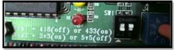
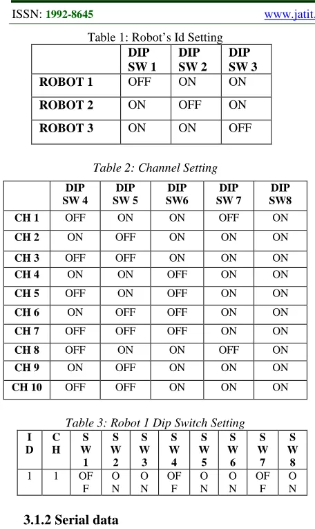
Based on soccer robot specification, there have two setting on the transmitter. Figure 2 below shows that the black box DIP switch is the settings for RF module type while the blue knob on the right of black box DIP switch is to setting the channel of wireless communication. Basically, this type of robot use 418L RF communication module which is can control up to 3 robots in the same channel. In Figure 3 shows 8 DIP switch on the receiver of the robot which is use to configure setting for communication module.
For DIP Switch from 1 to 3, it will represent the ID of the robot. While, the rest DIP Switch from 4 to 8 is to set channel. In Table 1 and Table 2 shows how to setting DIP switch on the mobile robot. In this considered only for robot one. The settings are as shown in Table 3.
Figure 2: Transmitter Setting
Figure 3: DIP Switch Setting
B
C N
N
Table 1: Robot’s Id Setting
Table 2: Channel Setting
Table 3: Robot 1 Dip Switch Setting
I
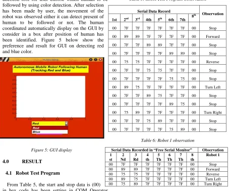
This data will be used to move the robot which is forward, reverse or stop. The Serial data record is show in Table 4.
Table 4: Serial Data Record
Serial Data Recorded in “ Free Serial Monitor” 1st 2nd 3rd 4th 5th 6th 7th 8th
Robot speed depends on the PWM value send from serial data. Each PWM value has difference speeds.
3.2 Software Development 3.2.1 Classification algorithm
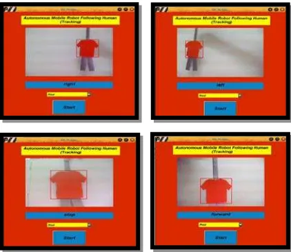
The first step in the algorithm is to recognize objects in an image captured by the camera. Then, the algorithm must detect the human by color. The user need to choose what color mobile robot need to follow which is red or blue. After user selection centroid of the human is determined. This centroid is then compared with the center of the image to get the location of the human with respect to the camera, either at the left or right of the camera. If the human is not in the center of the camera view, then corrective measures is taken so that the human will be in the center of the camera view.
The classification algorithms focus on the red color because red color gives better performance than blue color. This range of detection was influence by color wavelength. Theoretically, blue color wavelength was 450nm while red color wavelength was 620nm. Different wavelength between red and blue color are too much. Because of that the performance of red is better than blue. It is because wavelength of each color was depends on intensity. Intensity was the important thing to be considered while choosing pixel value. Less intensity causes blue color could not be detect at long distance. The classification algorithms flowchart is show in Figure 4.
ISSN: 1992-8645 www.jatit.org E-ISSN: 1817-3195
3.2.2 Graphical User Interface (GUI) design
In the preference of GUI, there must have a decision tool for user choose which human to be followed by using color detection. After selection has been made by user, the movement of the robot was observed either it can detect present of human to be followed or not. The human coordinated automatically display on the GUI by consider in a box after position of human has been identified. Figure 5 below show the preference and result for GUI on detecting red and blue color.
Figure 5: GUI display
4.0 RESULT
4.1 Robot Test Program
From Table 5, the start and stop data is (00) in hex code has been setting in COM Operator Software. However to control the robot speed and direction, only 2nd and 3rd byte represented for robot 1 and the others byte are to present for robot 2 and 3.Overall of the test is by using hex code data. This data must be converting into decimal code first. There are other information needs to be considered before control mobile robot speed. The conversion of significant code is shown in Table 7 and Table 8 shown ranges of value to control the direction of motor. As a summary, to more clear about robot operation, Table 6 shows the observation of robot movement but only focus on Robot 1 data.
To ensure that robot could move freely and smoothly, robot must be setting with the right value of Pulse Width Modulation (PWM) to control speed of the robot. Table 7 shows the conversation of the significant code and Table 8 show the range of values to control the direction of motor. By using the ranges value, the mobile robot movement can
be turn by changing time delay and PWM value for different condition.
Table 5: Robot Test Program Observation
Table 6: Robot 1 observation
Table 7: Conversion Of The Significant Code
Hex code
Decimal Code
Binary Code
Motor response 00 00 0000 0000
Anti-Clockwise 7F 127 0111 1111 Stop and Lock
FF 255 1111 1111 Clockwise Serial Data Record
Observation 1st 2nd 3rd 4th 5th 6th 7th 8
th
00 7F 7F 7F 7F 7F 7F 00 Stop
00 89 89 7F 7F 7F 7F 00 Forward
00 7F 7F 89 89 7F 7F 00 Stop
00 7F 7F 7F 7F 89 89 00 Stop
00 75 75 7F 7F 7F 7F 00 Reverse
00 7F 7F 75 75 7F 7F 00 Stop
00 7F 7F 7F 7F 75 75 00 Stop
00 89 75 7F 7F 7F 7F 00 Turn Left
00 7F 7F 89 75 7F 7F 00 Stop
00 7F 7F 7F 7F 89 75 00 Stop
00 75 89 7F 7F 7F 7F 00 Turn Right
00 7F 7F 75 89 7F 7F 00 Stop
00 7F 7F 7F 7F 75 89 00 Stop
Serial Data Recorded in “Free Serial Monitor” Observation 1
st 2 Nd
3 Rd
4 th
5 Th
6 Th
7 Th
8 th
Robot 1
Table 8: Range Of Values To Control The Direction Of The Motor
4.2 Classification Algorithms
The classification algorithms allow the user to make a choice on color detection either red or blue. Figure 6 show the preference and result for GUI on detecting red and blue color.
Figure 6: GUI For Tracking Color
Next phase was to combine color detection algorithm with mobile robot movement status show in Figure 7. The system finally able to control mobile robot and allow it to follow human and fulfill the requirement set up.
Figure 7: GUI With Mobile Robot Movement Status
5. DISCUSSION
Every data provide a different effect on robot movement. Mobile robot movement for forward and reverse, both 2nd and 3rd byte set by same value but for turn left and right required different value for 2nd and 3rd byte show in Table 4.0. It can be conclude that to move forward and reverse both wheel provide with same data to move while to turn on other movement data provide to move wheel might be different depends on what direction it will be.
The range of decimal code is from 00 until 255 because the less hexadecimal code is 0 and the greater code is FF. The decimal value gets from the conversation of the significant robot. To turn right direction value on 2nd byte must be greater than 3rd byte and otherwise. It is because 2nd byte will represent for left wheel while 3rd byte value will represent as right wheel of motor. Table 4.3 shows the range for direction of the motor. Pulse Width Modulation (PWM) of the motor must be setting well in order to get suitable speed for robot movement. This PWM value is the velocity of motor for both left and right motor.
To detect presence of red and blue color using static image is easier compare to detect that color on life image. It is because, for life image, the election of threshold and pixel value in the algorithm must be choosing correctly. Besides that, even same pixel value set for both color, but it results to different performance. By applying 300 pixels value the detection of color different from their range of detection.
The range between mobile robot and human was setting around 20cm as references means that mobile robot stop moving automatically if the range close at that range. Human moving closer to mobile robot from references range will act to reverse and otherwise.
6. CONCLUSION
As conclusion the user finally has an ability to choose which human to be followed instead of robot fixed on detecting only one person. The mobile robot also able to move following human depend on the user selection by color and can be control the mobile robot speed automatically. The Graphical User Interface (GUI) will display the human coordinate easy to monitor the mobile robot movement.
Decimal Code Motor Response
00 ≤ x ≤ 127 Anti-Clockwise x= 127 Stop and Lock
ISSN: 1992-8645 www.jatit.org E-ISSN: 1817-3195
7. RECOMMENDATION
The mobile robot could be including together with sensor to avoid obstacle during following human. Besides that, instead of detecting two kind of color, this system can be improved by detecting many colors. So this system can easily adapt with human environment.
8. ACKNOWLEDGMENT
The authors are grateful for the support granted by Universiti Teknikal Malaysia Melaka (UTeM) in conducting this research
REFERENCES
[1] Antonio .S, Olac .F & Angelica .M (2004). Development of Local Vision-based
Behaviors for a Robotic Soccer Player. IEEE, pg 275-281.
[2] Yasuke.N & Akihisa .O (2001). Human Following Behavior of an autonomous Mobile Robot Using Light-Emitting Device. IEEE, pg 225-230.
[3] Hairol Nizam Mohd Shah, Mohd Zamzuri Ab Rashid, Tam You Tam (2013), Develop and Implementation of Autonomous Vision Based Mobile Robot Folowing Human, International Journal of Advanced Science and Technology Vol. 51.
[4] Masafumi .H & Fuminori .O (1997). Mobile Robot Localization Using Color Signboard. IEEE, pg 111.
[5] LW Teck, M Sulaiman, HNM Shah, R Omar (2011), Implementation of Shape–Based Matching Vision System in Flexible
Manufacturing System, Journal of Engineering Science and Technology Review 3 (1), 128- 135
[6] Firmansyah I.,Hermantino B & Handoko L.T (2007). Control and Monitoring System for Modular Wireless Robot. Industrial
Electronics Seminar 2007.
[7] Songmin .J, Akira .Y, Daisuke .C & Kunikatsu .T (2008). Map Building for a Service mobile Robot Using Interactive GUI. International on
information and Automation Jun 20-23 2008, Zhangjiajie, China. pg 119-124.
[8] Kok-Meng. L, Fellow,IEEE, Qiang L & Wayne D (2007). Effect of Classification Methods on Color-based feature detection With food processing Applications. IEEE, pg 40-51.
[9] Dr. Kansei .I & Dr. Gabriel .M (1993). A Clor Classification Algorithm. IEEE, pg726-729. [10] Yujin Robotics Co., L. (2006). Soccer Robot- YSR - A 5vs5 System Manual (Meteor 2/4 type).
[11] Wunderlich, M. B. (2002). Development of Software for Mobile Robot Control over a Radio Frequency Communication Link. Proceedings IEEE SoutheastCon 2002, pg 414-417
[12] Yang Wang & David Lee (2006). Reinforcement Learning for a Human- Following Robot. The 15th IEEE Internatioanal Symposium on Robot and Human Communication (RO-MAN06), Hatfield U.K, pg 309-314.