3rd International Conference on Engineering and ICT (ICEI2012) Melaka, Malaysia
4 – 6 April 2012
ORIENTATION TRACKING WITH MEMS INERTIAL SENSORS
N.S.N Anwar
1,a*, A.M. Kassim
2,b, M.F Miskon
3,c, M.R. Yaacob
4,d1,2,3,4 UTeM/FKE, Durian Tunggal, Malaysia aEmail: [email protected] , bEmail: [email protected] cEmail: Third [email protected], d Email: [email protected]
Abstract—In many applications orientation tracking needs to be done, for example in inertial navigation, autonomous mobile robot, virtual reality or industries. This paper proposes a method of doing the orientation tracking using MEMS inertial sensors such as accelerometer, gyro and magnetoresistive sensor. The error problems with this type of sensors are discussed. As results, a comparison of measurements between the three sensors is made. Finally a recommendation on how sensor fusion algorithm could be implemented to get an accurate result.
Keywords—Orientation, tracking, inertial, navigation
I. INTRODUCTION
Human stabilization system which is built inside the inner ear is such a technology marvel considering its ability to function in complete darkness and without external reference. This ability is what we call as orientation tracking. If the ability could be applied in real technical application, it would contribute to a major improvement in many aspects. Possible applications of orientation tracking are in inertial navigation system such as an Inertial Measurement Unit, IMU, in virtual reality, medical technology and also in industries such as 3D compassing.
Measuring rotation directly is very difficult. Therefore rate of rotation (or angular rate) shall be measured using gyroscopes and integrated once to get the rotation. Starting from 1960s optical gyros was used in submarines and commercial aeroplanes. They make use of the Sagnac effect. This type of gyros is expensive however very accurate and stable.
In inertial navigation, the orientation of the moving compass to measure his heading direction with respect to true north. While the example is in 2D, the situation in 3D could be a little bit complicated.
In 1990s a new type of gyros appears which works on Coriolis effect. A proof mass is suspended by a spring system, that allows movement in two orthogonal directions, let say x-axis and y-axis. An oscillation of the mass along the x-axis is excited. If the sensor rotates around z-axis, the Coriolis force acts along the y-axis. As consequences the mass starts to oscillate along y-axis too. The amplitude of the oscillation is proportional to the angular velocity [1]. This sensor exists as low cost MEMS sensors and finds its application in automotive such as Electronic Stability Program.
II. METHODOLOGY
The proposed method is to use MEMS inertial sensor from AnalogDevice. Adis 16350 is a complete triple axis gyros and triple axis accelerometers. It is integrated with on chip mixed signal processing technology and produces digital outputs through the SPI bus. The other sensors like pressure sensor and magnetic sensors are connected to analog -to- digital converter chips.
A. Errors in MEMS inertial sensor
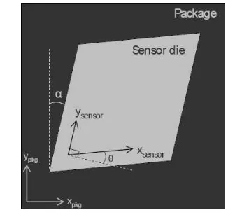
It has always been assumed that the sensors are mounted so that they build an orthogonal system. In reality a perfect physical alignment can never be achieved. The axis could 'lean' towards other axis with some angle. This is referred as nonorthogonality with unit (°).
Another type of error is the misalignment. Misalignment is the tilt error of the sensor with respect to the sensor housing. This error arises from the assembly tolerance of the sensors. The unit for misalignment is also (°).
Figure 1. Errors in MEMS sensor [2]
Table 1. The errors in the Gyro of ADIS 16350 sensor module
Error type Condition Value Unit
Nonorthogonality Different to 90° ideal
±0.05 deg
Misalignment Relative to base plate and
guide pins
±0.5 deg
Nonlinearity Best fit straight line
0.1 % of FS
Angular Random Walk
25°C 4.2 °/√hr
3rd International Conference on Engineering and ICT (ICEI2012) Melaka, Malaysia
4 – 6 April 2012
both. The direction extracted from gyros is always relative to a reference, while the direction from the magnetic compass is absolute (True North).
B. Correction with gravitational acceleration
The accelerometers cannot differentiate between gravitational acceleration and acceleration from the real motion. Due to this, the recalibration can only take place when the object is in stationary. The rotation angles from the acceleration sensor can be calculated as follows.
(1)
(2)
(3)
Figure 2. Rotation angle calculation from accelerometer
However since arctan will only produce angles in the range of ±90°, the rotation angles calculated from formula (X) will jump from one quadrant to another. For this we need to do a correction, where we subtract 180° from the angle if the difference between two successive angles is greater than 90°. If the difference is -90° we will add 180°.
Figure 3. Jumping angles from the arctangent calculation
C. Correction with magnetic sensing
The earth magnetic field intensity is about 0.5 to 0.6 gauss and has a component parallel to the earth's surface that always point toward magnetic north. The angle of the magnetic field to the surface of the earth is called the dip, or inclination angle and varies with the latitude. For Aachen, the dip is roughly 70° down toward the north. Only the X and Y components of the earth's magnetic field is used when determining the True North [3].
Figure 4. Angle calculation from earth’s magnetic field III. RESULTS AND ANALYSIS
For the result, few simple experiments have been done using the sensor. In the experiments some controlled motions such as translational and rotational motion were applied to the sensor and the inertial data were logged using a PC.
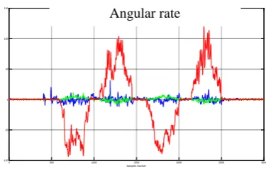
In this experiment, the sensor was turned 90° about the Z-axis, and reversed. The sensor was in static position and should be only under gravitational acceleration.
Figure 5. Acceleration result from the turning motion
Figure 6. Angular rate (Gyro) result from the turning motion 0 500 1000 1500 2000 2500 3000 -1.5
-1 -0.5 0 0.5 1 1.5
Input1(blue),Input2(green),Input3(red) and Input4(magenta)
Samples Number
0 500 1000 1500 2000 2500 3000 -100
-50 0 50 100 150
Input1(blue),Input2(green),Input3(red) and Input4(magenta)
Samples Number Uncorrected angle vs samples
A ng les (D eg re e)
Acceleration
3rd International Conference on Engineering and ICT (ICEI2012) Melaka, Malaysia
4 – 6 April 2012
Figure 6. Magnetic field result from the turning motion
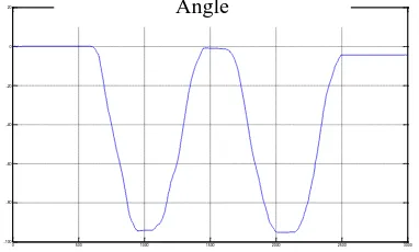
Figure 6. Angle calculation from the Gyro for the turning motion
IV. CONCLUSION
In conclusion it was proven that it is possible to do orientation tracking using the gyros. However the result could deviate after a long time. The information from the accelerometer and magnetometer should be used in a sensor fusion algorithm to recalibrate the gyro sensor from time to time.
ACKNOWLEDGMENT
The author would like to thank Universiti Teknikal Malaysia Melaka for the financial support in the research. Also the Divenav team members from University of Applied Science Aachen who had started the project, in which the author was one of the member while doing his Master in 2010.
REFERENCES
[1] Kämper, Klaus Peter, Lecture Notes Sensors and Actuators, FH Aachen
[2] MEMS Sensor Lexicon. www.analog.com
[3] Caruso, J. Michael Applications of Magnetoresistive Sensors inNavigation Systems. Honeywell
[4] Woodman, Oliver J. An Introduction to inertial navigation. University Cambridge , 2007
[5] Weinberg, Harvey Calibrating iMEMS Gyroscopes., [6] Hai, Markus ,Verfahren und Vorrichtung zum Ausführen einer
Objektverfolgung. Fraunhofer Institute, 2004
0 500 1000 1500 2000 2500 3000 -500
-400 -300 -200 -100 0 100 200 300 400 500
Input1(blue),Input2(green),Input3(red) and Input4(magenta)
Samples Number
0 500 1000 1500 2000 2500 3000 -100
-80 -60 -40 -20 0 20
Magnetic Field Strength