CHAPTER II
LITERATURE REVIEW
AISC Seismic Provisions for Structural Steel Buildings (AISC 341-2005) were used to design steel structure with the needs of high ductility level (R> 3). R is the seismic response modification coefficient.
II.1 Load and Resistance Factor Design (LRFD)
In the load and resistance factor design, the design satisfied the requirements if the minimum of design strength is equal to the required strength which determined by the load combination for LRFD calculation.
Design shall be performed in accordance with equation: Ru ≤ ØRn
Where: Ru= required strength (LRFD)
Rn= nominal strength
Ø = resistance factor; 0.9 for yielding or compression buckling and 0.75 for rupture (fracture)
ØRn = design strength
The load combinations are: 1. 1.4 (D+F)
2. 1.2 (D+F+T) + 1.6 (L+H) + 0.5 (Lr or S or R)
3. 1.2D + 1.6 (Lr or S or R) + (0.5L or 0.8W)
5. 1.2D + 1.0E + 0.5L + 0.2S 6. 0.9D + 1.6W + 1.6H 7. 0.9D + 1.0E + 1.6H Where: D = dead load E = Earthquake load
F = load due to fluids with well-defined pressures and max heights
H = load due to lateral earth pressure, groundwater pressure, or pressure of bulk materials
L = live load Lr = roof live load
R = rain load S = snow load
T = self-straining force W = wind load
II.2 Compression Members
Compression members are the elements of the structure that only have an axial compressive forces, f = P/A, where f is considered become uniform among the entire cross section. One of the compression members is column.
For LRFD: Pu ≤ ØcPn
Where: Pu = sum of the factored loads
Øc= resistance factor for compression = 0.9
ØcPn= design compressive strength
The flexural buckling stress, Fcr, is determined as follows:
a. When ꆐ.
i 4 71 , Fcr = 0 658
b. Whenꆐ.
i 4 71 , Fcr = 0.877 Fe
Where Fe = elastic critical buckling stress
Fe = 齠 u
II.3 Beams
Beams are the member of the structure that can support transverse loads and mainly subjected to flexure or bending. For flexure, the design moment in the LRFD:
Mu ≤ ØbMn
Where: Mu = required moment strength
Øb = resistance factor for bending (flexure) = 0.9
Mn = nominal moment strength
According to the limit states of yielding (plastic moment) and lateral-torsional buckling, the nominal flexural strength, Mn, should be in
Where My is the bending moment that makes the beam to the
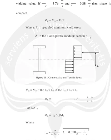
yielding value. If
I 3 76 and n 0 38 then shape is
compact,
Mn = Mp = Fy Z
Where: Fy = specified minimum yield stress
Z = the x-axis plastic modulus section =
n
Figure II.1 Compressive and Tensile Stress
Mn = Mp if the Lb ≤ Lp, if the Lp < Lb ≤ Lr
Mn = 0 7 . ..
u .
For Lb>Lr
Mn = Fcr S ≤Mp
Where
Fcr =. /i齠
r 1 0 078S . i r
n
When the shape is non compact, for flange local buckling: If λ ≤λp, there is no flange local buckling
If λp< λ ≤λr, Mn = 0 7
[image:4.595.88.511.142.675.2]For lateral-torsional buckling:
If Lb ≤ Lp, there is no lateral-torsional buckling
If Lp < Lb ≤ Lr,
Mn = 0 7 . .
.u .
If Lb > Lr, Mn = Fcr S ≤ Mp
Beside the design moment, beam also has shear strength that need to be considered. The nominal strength of shear, Vn, of unstiffened or
stiffened webs, according to the limit states of shear yielding and shear buckling, is
Vn = 0.6 Fy AwCv
Where: Aw = area of the web
d = overall depth of the beam
Cv = ratio of critical web stress to shear yield stress
For web of rolled I-shaped members, Cv = 1.0 and LRFD Øv = 1.0,
other than it, except round HSS, the Cv is determined:
1. For h/tw ≤ 1.10 / , Cv = 1.0
2. For1 10
(I 1 37 / , Cv =
䅀 䅀Ƽ /
/(I
3. For
(I 1 37 / , Cv =
䅀 Ǵ䅀 /(I
The relationship between required and available strength is (LRFD)
Vu Øv Vn
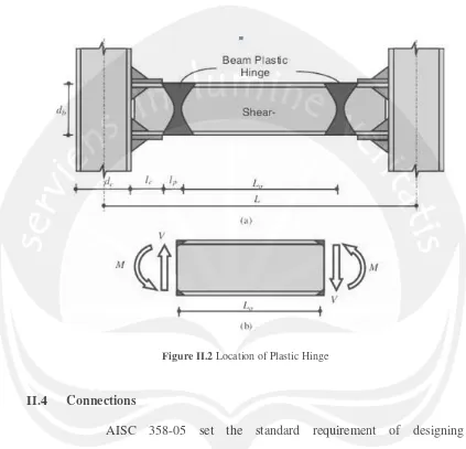
Vu = maximum shear based on the controlling combination
[image:6.595.89.512.163.570.2]aa of factored loads
Figure II.2 Location of Plastic Hinge
II.4 Connections
AISC 358-05 set the standard requirement of designing connections for use with Special Moment Frames (SMF) and Intermediate Moment Frames (IMF). Connections designed in AISC 358-05 can be used for structures with LRFD or ASD provisions for the AISC Seismic Provisions.
Figure II.3 Steel Beam to Column Connection
II.4.1 Connection Design
It has been mentioned above that to design the connection it should refer to the strength of the bracing, that set as Ry Fy Ag. It means, the
strength of the connection should be greater than the bracing connection. it can be written as,
Pconnection > Ry Fy Ag
Which is if the connection is designed using bolted or welded, than it should be design to withstand the stress from the bracing.
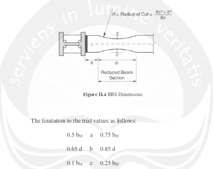
II.5 Reduced Beam Section
to-column connection. Yielding and hinge formation are intended to occur primarily within the reduced section of the beam.
[image:8.595.88.511.221.557.2]To design using RBS procedure the beam section, column section and the RBS dimension must be through trial values a, b, and c.
Figure II.4 RBS Dimensions
The limitation to the trial values as follows: 0.5 bbf a 0.75 bbf
0.65 d b 0.85 d 0.1 bbf c 0.25 bbf
The plastic modulus will be at the center of reduced beam section. (Ze = Zx
− 2ctbf (d − tbf )).
Maximum probable moment at the center of the reduced beam section can be determine by i . The values of Cpr shall not be
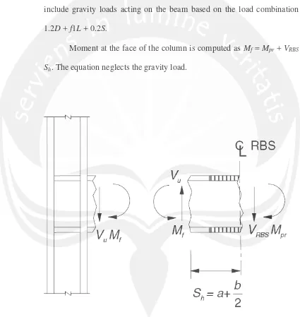
The shear force at the center of the reduced beam sections shall be determined by a free body diagram of the portion of the beam between the centers of the reduced beam sections. This calculation shall assume the moment at the center of each reduced beam section is Mpr and shall
include gravity loads acting on the beam based on the load combination 1.2D + f1L + 0.2S.
Moment at the face of the column is computed as Mf = Mpr + VRBS
[image:9.595.87.512.218.667.2]Sh. The equation neglects the gravity load.
Plastic moment can be calculated by Mpe = ZbRyFy. The plastic
moment should not bigger than moment at the face of the column (Mf).
The required strength Vu will be calculated as follows n u
.
뵈ig )( The design of shear strength of the beam refers to AISC
Specifications chapter G.
To check the column-beam moment ratio ∑ i . Mv
is 鍈BS
n n .
II.6 Shear Influence in Beam Moment Capacity
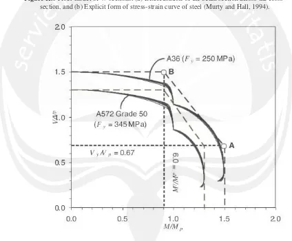
Figure II.6 Fiber model of W-sections: (a) Discretisation of the beam section across the cross-section, and (b) Explicit form of stress-strain curve of steel (Murty and Hall, 1994).
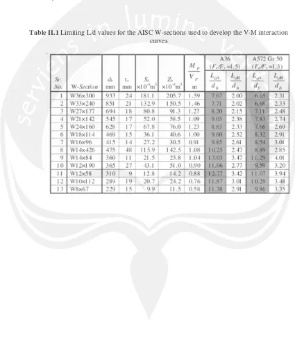
Figure II.7 Normalized V-M interaction surfaces for AISC W-sections with idealized upper bound forminimum specified yield strength and Fu/Fy = 1.5 (Fy = 250 MPa) and Fu/Fy = 1.3
(Fy = 345 MPa), and Ry=1.0
[image:11.595.87.511.288.638.2]moment and shear that are expected to be developed in the beam. In the existing method for design of beams, a section with Mp larger than the
[image:12.595.83.508.210.700.2]maximum bending moment demand M is selected. It is then ensured that Vp of the section is larger than the maximum shear demand V.
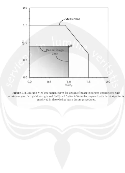
Figure II.8 Limiting V-M interaction curve for design of beam to column connections with minimum specified yield strength and Fu/Fy = 1.5 (for A36 steel) compared with the design limits