KESIMPULAN DAN SARAN EVALUASI KINERJA REDUCED BEAM SECTION PADA STRUKTUR BAJA TAHAN GEMPA DENGAN ANALISIS PUSHOVER.
Teks penuh
Gambar
Dokumen terkait
PADA STRUKTUR BAJA TAHAN GEMPA , Andry Sanjaya Tandani, NPM 080213153, tahun 2012, PPS Struktur, Program Studi Teknik Sipil, Fakultas Teknik Universitas Atma
baja dengan menggunakan sistem struktur rangka bresing konsentrik1.
lateral efektif dapat diambil dari kekakuan secant yang dihitung dari gaya geser dasar. sebesar 60% dari kuat
Gambar 5.5 Lokasi Terjadinya Sendi Plastis dari Hasil Analisis Time History untuk Bangunan 4-lantai pada Portal Eksterior 100 Tahun ……… 21.. Gambar 5.6 Lokasi Terjadinya
Gambar 5.13 Lokasi Terjadinya Sendi Plastis dari Hasil Analisis Time History untuk Bangunan 4-lantai pada Portal Eksterior 1000 Tahun ……… 25 Gambar 5.14 Lokasi Terjadinya
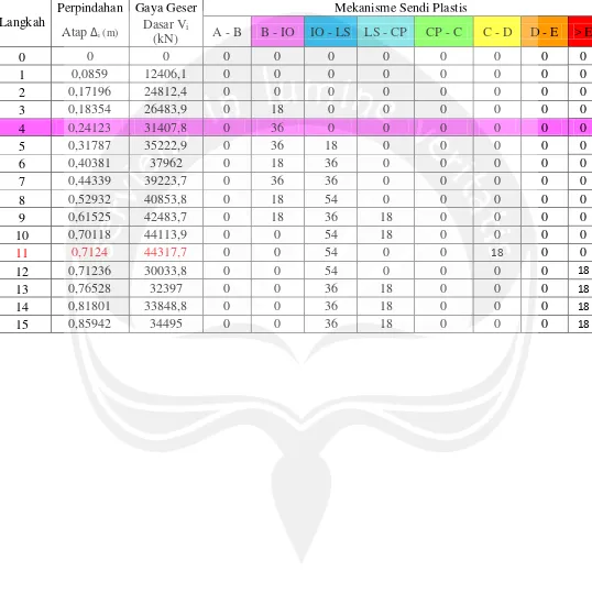
Metode pushover adalah suatu analisis statik nonlinier dimana pengaruh gempa rencana terhadap struktur bangunan gedung dianggap sebagai beban-beban statik yang menangkap
Metode pushover adalah suatu analisis statik nonlinier dimana pengaruh gempa rencana terhadap struktur bangunan gedung dianggap sebagai beban-beban statik yang menangkap pada
Fakultas Teknik UNS berada pada batas antara Life Safety (LS) - Collapse Prevention (CP) dengan sendi plastis telah terjadi pada kolom. Berdasarkan kriteria SNI
