DESIGN AND ANALYSIS OF JACKING POINT STRUCTURE TO LIFT HEAVY-WEIGHT CRUDE OIL TANK
FOR ANNULAR PLATE MAINTENANCE
NORHAZREEL SAIFULLAH BIN BAHARIN
SUPERVISOR DECLARATION
“I hereby declare that I have read this thesis and in my opinion this report is sufficient in terms of scope and quality for the award of the degree of
Bachelor of Mechanical Engineering (Automotive)”
Signature: ………
Supervisor: FEBRIAN BIN IDRAL
DESIGN AND ANALYSIS OF JACKING POINT STRUCTURE TO LIFT HEAVY-WEIGHT CRUDE OIL TANK
FOR ANNULAR PLATE MAINTENANCE
NORHAZREEL SAIFULLAH BIN BAHARIN
This thesis is submitted in partial fulfillment of the requirement for the
Degree of Bachelor in Mechanical Engineering (Automotive)
Faculty of Mechanical Engineering Universiti Teknikal Malaysia Melaka
DECLARATION
“I hereby declare that the work in this thesis is my own except for summaries and quotations which have been duly acknowledged.”
Signature: ………
Author: NORHAZREEL SAIFULLAH BIN BAHARIN
iii
ACKNOWLEDGEMENT
First of all, praise is to Allah for protecting us in whatever activity that we had done. I would like to express my full appreciation to all those who always supporting me to complete this report.
v
ABSTRACT
ABSTRAK
vii
CONTENT
CHAPTER TOPIC PAGE
DECLARATION ii
DEDICATION iii
ACKNOWLEDGEMENT iv
ABSTRACT v
ABSTRAK vi
CONTENT vii
LIST OF TABLES x
LIST OF FIGURES xi
LIST OF SYMBOLS xiv
LIST OF ABBREVIATION xv
I INTRODUCTION 1
1.1 INTRODUCTION 1
1.2 PROJECT OBJECTIVES 1
1.3 PROJECT SCOPES 2
1.4 PROBLEM STATEMENT 2
1.5 METHODOLOGY VIEW 3
II LITERATURE REVIEW 5
2.1 INTRODUCTION 5
2.2 STORAGE TANK 5
2.2.1 Type and Material Contents 6
2.3 TANK ACCIDENT 8
CHAPTER TOPIC PAGE
2.3.2 Corrosion 9
2.3.3 Seismic Motion (Tilting) 11
2.4 MAINTENANCE PURPOSE OF STORAGE
TANK 13
2.5 FAILURE THEORIES 13
2.6 DISTORTION ENERGY THEORY 14
2.7 WIND LOAD 17
2.8 JACKING SYSTEM 18
2.8.1 Strand Jack 18
III DESIGN CRITERIA 20
3.1 INTRODUCTION 20
3.2 TANK PARAMETER 20
3.2.1 Tank Loading 22
3.3 WIND LOAD 23
3.4 STRUCTURAL MATERIAL 24
3.4.1 Steel 24
3.4.1.1 Carbon Steel 25
3.5 PRODUCT SPECIFICATIONS 26
3.6 PRODUCT CONFIGURATIONS 27
IV METHODOLOGY 29
4.1 INTRODUCTION 29
4.2 MORPHOLOGICAL CHART 29
4.3 CONCEPTUAL DESIGN 31
4.3.1 Conceptual Design of Jacking point
structure 31
4.4 WEIGHTED DECISION MATRIX METHOD 36
4.4.1 Evaluation and Scoring Result 38
4.5 THREE BEST CONCEPTS 39
ix
CHAPTER TOPIC PAGE
V RESULT AND DISCUSSION 45
5.1 INTRODUCTION 45
5.2 ANALYSIS OF CONCEPTUAL DESIGN 45
5.2.1 CATIA Result on FEA Analysis 47
5.2.1.1 Concept 1 49
5.2.1.2 Concept 3 50
5.2.1.3 Concept 5 51
5.2.2 Result Analysis 52
5.3 CHOOSING CONCEPTUAL DESIGN 54
5.4 DESIGN OPTIMIZATION 55
5.5 ANALYSIS OF CRUDE OIL TANK’S MODEL 57
5.6 WIND LOAD ANALYSIS 60
5.7 DESCRIPTION OF THE JACKING
OPERATION 62
VI CONCLUSION 63
6.1 CONCLUSION 63
6.2 RECOMMENDATION 63
REFERENCES 65
BIBLIOGRAPHY 68
LIST OF TABLES
NO. TITLE PAGE
2.1 Type of tanks and its content (Chang and Lin, 2006) 7 2.2 Cause of tank accidents from year 1960 to 2003 (Chang
and Lin, 2006) 9
3.1 Parameters of Tank Shell 22
3.2 Chemical Properties for ASTM A283 Grade C 25
3.3 Mechanical Properties for ASTM A283 Grade C 26
4.1 Morphological Chart for Jacking point structure 30 4.2 Weighted Decision Matrix for Jacking point structure 37 4.3 Evaluation Scheme for Design Criteria of Jacking point
structure 39
5.1 Total mass of selected concept designs 48
5.2 Analysis result of conceptual designs 54
5.3 Comparison of analysis result before and after the
xi
LIST OF FIGURES
NO. TITLE PAGE
1.1 Methodology Chart 4
2.1 Storage tank 6
2.2 Dome, floating and cone roof type of storage tank. 7
2.3 Tank accident 8
2.4 Fracture of the supporting structure of storage tank due to
corrosion 10
2.5 Oil leaking area 12
2.6 Element faced with tri-axial stresses 15
3.1 Schematic diagram of storage tank 21
3.2 Dimensions for sample design of jacking point structure 26 3.3 Location of jacking point structures around the tank's wall 27 3.4 Section view of the jacking point structure installed on the
tank's shell 28
4.1 Concept 1 32
4.2 Concept 2 33
4.3 Concept 3 34
4.4 Concept 4 35
4.5 Concept 5 36
4.6 Objective tree for the design of a jacking point structure 38
4.7 Concept 1 40
4.8 Concept 3 40
4.9 Concept 5 40
NO. TITLE PAGE
4.11 Dimension of Concept 1 42
4.12 Detail drawing of Concept 3 42
4.13 Dimension of Concept 3 43
4.14 Detail drawing of Concept 5 43
4.15 Dimension of Concept 5 44
5.1 Restrain area and applied load position for Concept 1 46 5.2 Restrain area and applied load position for Concept 3 47 5.3 Restrain area and applied load position for Concept 5 47
5.4 Maximum Von Mises stress on Concept 1 49
5.5 Maximum deflection on Concept 1 49
5.6 Maximum Von Mises stress on Concept 3 50
5.7 Maximum deflection on Concept 3 50
5.8 Maximum Von Mises stress on Concept 5 51
5.9 Maximum deflection on Concept 5 51
5.10 Von mises stress for selected conceptual designs against
applied load 52
5.11 Maximum deflection for selected conceptual designs
against applied load 53
5.12 Modification of Concept 1 55
5.13 Maximum Von Mises stress on improved design of jacking
point structure 56
5.14 Maximum deflection on improved design of jacking point
structure 56
5.15 Jacking point structure installed and the jacking load
position 57
5.16 The clamping and jacking load position on the tank’s
model 58
5.17 Von Mises stress analysis on the tank's model 58
5.18 Von Mises stress in closed view 59
xiii
NO. TITLE PAGE
5.20 Deflection contour in closed view 60
5.21 Top view of the crude oil tank and the direction of wind
load. 60
5.22 Side view of crude oil tank and the direction of wind load. 61 5.23 Selected concept design attached on the tank's wall 62
A Image of floating roof type crude oil tank 69
B Properties of A283 carbon steel obtained from ASTM
LIST OF SYMBOLS
qz = Velocity Pressure, N/m2
Kz = Velocity Pressure Exposure Coefficient Kzt = Topographic Factor
Kd = Wind Directionality Factor
V = Wind Gust Speed, m/s
P = Pressure, N/m2
xv
LIST OF ABBREVIATION
ASCE American Society of Civil Engineers AISC American Institute of Steel Construction ASTM American Society for Testing and Materials API American Petroleum Institute
CATIA Computer Aided Three-dimensional Interactive Application FEA Finite Element Analysis
1 CHAPTER I
INTRODUCTION
1.1 INTRODUCTION
The crude oil tank is a large structure built to store crude oil after drilling process. The content is stored in this tank before undergoing a distillation process to separate the hydrocarbon type such as petroleum, gas, naphtha, gasoline, kerosene, diesel, lubricating oil, heavy gas and the residues. In this project, one of the crude oil tank is located in Port Dickson, Malaysia which owned by Petron Malaysia Berhad. It is a floating roof type of storage tank built in 1962 which able to store up to 34 million liter crude oil. After 5 decades of service, maintenance project is proposed to service the annular plate of the tank which is located at the bottom. The tank structure needs to be lifted up for the maintenance process on the ground structure. However, there are no jacking points attached at the tank for jacking device installation.
1.2 PROJECT OBJECTIVES
The objectives of this study are:
To design jacking point structure and its configuration for crude oil tank jacking operation.
2
1.3 PROJECT SCOPES
Literature review on the engineering requirement for jacking operation, designing process and structural analysis of jacking members.
Conceptual design of jacking point structure.
Selection of conceptual design by using Weighted Decision Matrix Method. Detail design of the jacking point structure and perform structural analysis
using CATIA V5 R20 software for crude oil tank jacking process.
Selection of final design based on required criteria such as simple and safe design.
1.4 PROBLEM STATEMENT
Crude oil was an initial substance before undergoing a distillation process to produce useful fuel such as petroleum gas, gasoline and so on. Due to its long period of service for the storage tank, the changes in ground structure which annular plate has been detected under the tank’s body. The change and ground structure effect can caused damage on the tank structure. The concerns of this defect will cause a major problem such as the damage on the tank’s shell due to the tilt condition of the tank structure.
optimization due to reduce the cost of installation and fabrication by only selecting the best design following specifications required.
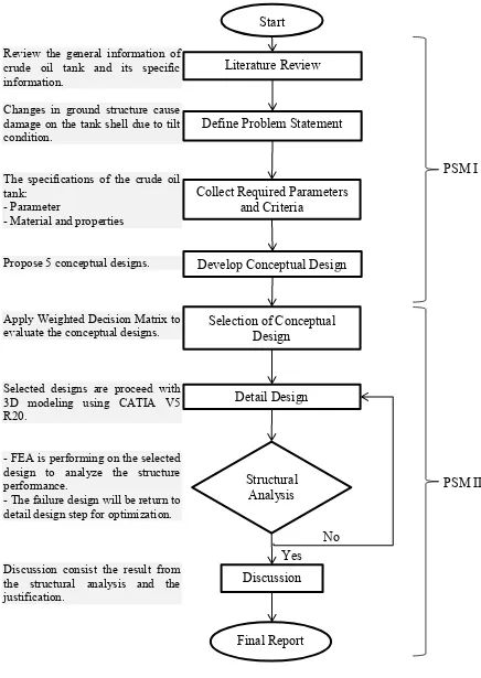
1.5 METHODOLOGY VIEW
4
Figure 1.1: Methodology Chart Start
Literature Review
Define Problem Statement
Collect Required Parameters and Criteria
Develop Conceptual Design
Selection of Conceptual Design Detail Design Structural Analysis Discussion Yes No Final Report PSM I PSM II
Review the general information of crude oil tank and its specific information.
Changes in ground structure cause damage on the tank shell due to tilt condition.
The specifications of the crude oil tank:
- Parameter
- Material and properties
Propose 5 conceptual designs.
Apply Weighted Decision Matrix to evaluate the conceptual designs.
Selected designs are proceed with 3D modeling using CATIA V5 R20.
- FEA is performing on the selected design to analyze the structure performance.
- The failure design will be return to detail design step for optimization.
2 CHAPTER II
LITERATURE REVIEW
2.1 INTRODUCTION
This section explains the literature review of the storage tank itself, the type of tank, type of accidents and the causes of accidents. Besides, the engineering characteristics related to this project are included such as material deflection and related stress involved in this case. The explanation is continued for the method to define Factor of Safety which is the important value in engineering failure analysis. Furthermore, the process of design and analysis of the tank and jacking point structure model is described such as, generating and evaluating of the concept design, and lastly the most important structural analysis process by using Finite Element Analysis (FEA) method. The source of information was collected from variable source such as published standard code of design, academic journal and book.
2.2 STORAGE TANK
6
tubing, forgings, and bolting. Basically, the important parts in storage tanks which calculations applied are the annular plate, shell and roof.
Figure 2.1: Storage tank (Source: www.parstechnic.com)
2.2.1 Type and Material Contents
Figure 2.2: Dome, floating and cone roof type of storage tank. (Source: www.parstechnic.com)
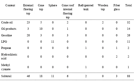
[image:24.595.101.546.382.652.2]Table 2.1 states the type of storage tank and its respective content, the information is collected by Chang and Lin (2006) for the study of storage tank accidents from years 1960 to 2003. However, the number of storage tank is continuing to increase due to the growth of oil and gas industry.
Table 2.1: Type of tanks and its content (Chang and Lin, 2006)
Content External
floating top
Cone
top Sphere Cone roof internal floating
top
Refrigerated
tank Wooden top Fiber glass Total
Crude oil 23 5 0 2 0 2 0 32
Oil products 3 10 0 1 0 0 0 14
Gasoline 20 3 0 3 0 0 0 26
LPG 0 0 11 0 0 0 0 11
Propane 0 0 0 0 1 0 1 2
Hydrochloric
acid 0 0 0 0 0 0 2 2
Methyl
cyanate 0 0 0 0 1 0 0 1
Subtotal 46 18 11 6 2 0 3 88