DOI: 10.12928/TELKOMNIKA.v15i1.3961 264
Intelligent Control of Wind/Photovoltaic Microgrid
Information Fusion
Jianhong Zhu*1, Wen-xia Pan2
1,2
College of Energy and Electrical Engineering, HoHai University, No.8, fo cheng xi Rd., Jiangning District, Nanjing City, Jiangsu Province, China
1
Institute of Electrical Engineering, NanTong University,
No.9, Seyuan Rd., Chongchuan District, NanTong City, Jiangsu Province, China *Corresponding author, e-mail: [email protected]
Abstract
A full-function Micro-grid must have an advanced energy storage device. Intelligent control with multi-information fusion was proposed either in energy storage or in grid connection control on this paper. Control targets were acquired by mixed application of various strategies, including Micro-grid peak load shifting be used to reduce State Utility Grid (SUG) supply pressure, SUG connection be controlled flexibly to maintain Micro-grid load working reliably, Micro-grid power production and load supply demands of SUG and Micro-grid be predicted to plan battery energy storage in advance, actual monitoring date be used to control overcharge and over-discharge, State of Charge (SOC) be managed to realize battery efficient storage and full life cycle as far as possible. All designs were integrated with forecasting and monitoring data from different measuring points, such as Micro-grid supply side and demand side, the SOC of storage system, the active and reactive power from SUG side, so as to control the battery charge and discharge behavior and SUG connection operation dynamically. Micro-grid could not only operate stand-alone by self-supply in most cases, in the case of power production surplus or equipment malfunction, the Micro-grid could also delivery energy to SUG or take power from the SUG flexibly. The scheme used fully of new energy, could ensure region power supply reliably and be used widely in application
Keywords: wind/photovoltaic/storage micro-grid, information fusion, intelligent control, peak load shifting, battery life
Copyright © 2017 Universitas Ahmad Dahlan. All rights reserved.
1. Introduction
As a new alternative energy, small wind and solar complementary generation system is always operated in Micro-grid island mode, also as a distributed generation technology used in group buildings [1]. The use of wind and solar complementary power can solve problems to a certain extent of environmental pollution and energy exhaust caused by the use of traditional energy sources, but the unique uncertainty and randomness of wind and solar generation power create major obstacles to the power generation and supply demand management [2], which show inherent shortages of centralized control or distributed control, wind and photovoltaic Micro-grid system is difficult to provide continuous and stable energy output [3]. In general, Wind/ Photovoltaic Micro-grid storage technology appeared in literatures are mostly focused on single function of maximum power tracking or analysis of battery capacity or operation method. Few are focused on proactive energy storage planning from the angle of the multi-objective control, such as battery charge and discharge protection, reliable power supply of Micro-grid load and peak load shifting, so as to achieve flexible and efficient control.
Micro-grid system. Literature [10] proposes a hybrid energy storage structure consisted of ultra-capacitor and battery, which can prevent battery from too large charge and discharge current resulting from power fluctuations and keep battery in an effective service life. To meet user more needs and improve the efficiency of the system, a more reliable charge and discharge control system must be used as a support [11].
In this context, the subject of intelligent control with multi-information fusion concept is proposed in this paper expanded on Wind/Photovoltaic Micro-grid storage systems. A plurality of information as SUG (State Utility Grid) load forecasting and Micro-grid power generation and load demand prediction are considered at the same in intelligent control. Stage planning is done for battery charge and discharge within the next 24 hours, solving the shortage problem of power generation of Micro-grid that may be happened during the future peak time of SUG load. So peak load shifting to valley and stagger supply power away from SUG peak are achieved under SUG connection, relieving the SUG supply pressure. At the same time, according to the Micro-grid power production forecast, a further SOC is predicted effectively to prevent battery from overcharge or over-discharge, thereby extending battery life.
2.Wind/Photovoltaic Storage System Topology
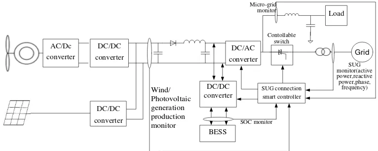
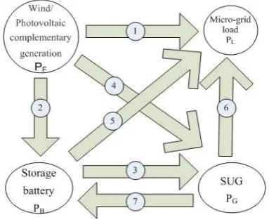
Wind/ Photovoltaic storage power generation system consists of five functional blocks. From the point of view of energy flows, there are multiple path divisions. The first is complete energy transmission from Wind/ Photovoltaic complementary power generation to Micro-grid load. The second is from Wind/ Photovoltaic complement power generation to battery energy storage system. The third is from the SUG to Micro-grid load. The fourth is two-way bi-direction power transmission from SUG to battery storage. The fifth is from Wind/ Photovoltaic complementary power generation to the SUG. According to the system function module structure analysis, the topology diagram designed is as shown in Figure 1, Wind/Photovoltaic complementary power generation supplies local Micro-grid load through the DC/AC converter. Battery is given an access to DC bus by DC-DC converter. As can be seen from the figure, to achieve energy management and intelligent control, monitor equipment must be placed firstly at the different locations, such as output port of DC-DC converter of Wind/ Photovoltaic power, the output port of storage system, the port of Micro-grid load, the port of SUG. So Wind/ Photovoltaic power generation production, SOC of battery, load supply demand and SUG parameters are monitored. Then based on the each monitoring parameter, combined with relevant forecasting data, information fusion is used to control battery charge and discharge and SUG connection flexibly by the intelligent controller.
Grid Load
AC/Dc converter
DC/DC
converter
DC/DC
converter
BESS DC/DC converter
DC/AC
converter
Wind/ Photovoltaic generation production
monitor SOC monitor
SUG monitor(active power,reactive power,phase,
frequency) Micro-grid
monitor
Contollable switch
SUG connection smart controller
Figure 1. Hybrid Systems of Wind/Photovoltaic/Energy Topology Schematic
3. Wind/Photovoltaic Storage Intelligent Control
done every 24 hours, so as to ensure Micro-grid self-supply operation during peak periods as far as possible, relieving the supply pressure of the SUG. Secondly, battery charging and discharging SOC range are controlled feasibly under intelligent controller, so overcharge or over-discharge is avoided, an effective life is extended. Finally, energy storage systems, Micro-grid new energy power generation system and SUG connection controller work in coordination to ensure long-term reliable operation of the Micro-grid. Specific control of energy flows is as shown in Figure 2. Generally, Wind/ Photovoltaic power generation system works in the form of Micro-grid stand-alone, once the generation surplus occurs, the storage battery is charged. When generation production is too high, and the same time SOC of battery is in full, Micro-grid connection is started to transport the surplus power to the SUG. In contrast, when Micro-grid fault or low Wind/ Photovoltaic generation production and low battery SOC occurs, SUG connection is triggered to supply power to Micro-grid load from SUG. The main advantage of the intelligent control is that Wind/Photovoltaic power output forecast and load demand prediction value are used as basis for the charge and discharge storage control, combined with the battery SOC, the further dynamic SUG connection control demand signal is given out. In Figure 1, when the system power production is greater than the electricity load demand, off-grid system is touched, power production surplus of Micro-grid is stored, the system intelligent controller controls the energy flown as shown in Figure 2 . When the battery SOC reaches 0.8, SUG is started connection to deliver energy to the SUG, the controller controls the energy flow as shown in Figure 2 . When electricity demand of Micro-grid load is greater than the generation production, Wind/ Photovoltaic power system collaborates with the battery to supply Micro-grid load demand, the controller controls the energy flow as shown in Figure 2 . When the battery SOC is down to 0.2, SUG connection is started together to supply local Micro-grid load. The system controller controls the energy flow as shown in Figure 2 . Once SUG electric load be in low valley, intelligent controller starts SUG connection to charge the battery, energy flow is controlled as shown in Figure 2 . When the Micro-grid electricity load demand equals to Micro-grid power production, Micro-grid supplies the local load stand-alone. Intelligent controller controls the energy flow as shown in Figure 2 . In the case of continuous rainy weather without wind, Micro-grid systems starts SUG connection to guarantee local power stable supply, the controller controls the energy flow as shown in Figure 2 .
relationship of Micro-grid power and load˄PF-PL)
SUG SUG load Micro-grid power Micro-grid load
t
t1 t2 t3 t4 t5 t6 t7 t8 t9 t10t11t12
0
PL
PF
P
tFigure2.Energy TransferSystem Schematic Figure3.24 HoursPredictionCurve of Grid andMicro-Grid
4. Intelligent Management Strategy Based Multi-information
4.1. Storage Strategy for Shifting Peak Load to Valley
During the period of load supply peak of SUG, if the Micro-grid power production is insufficient, and energy storage is not enough to supplement supply to local load as well, once SUG connection is started to supply Micro-grid load, SUG supply pressure would be aggravated. Clearly, the Micro-grid energy storage systems plan must be done as far as possible to maintain the Micro-grid reliable operation during peak period by energy replenishing, not only reducing power supply pressure on the SUG and achieving peak load shifting, but also reducing Micro-grid operating costs. Energy storage plan covers a wide forecast information, which includes the next 24-hour period Micro-grid power production forecast, Micro-grid and SUG load forecasting. Detailed plan of charging and discharging behavior for the next 24 hours is done based on the current battery SOC. For example, the SUG load forecast and Wind/ Photovoltaic power production forecast and Micro-grid load supply demand within 24 hours are shown as in Figure 3, where tk represents k moment, t1 represents L moment. PFt represents Micro-grid power production at t moment. PLt represents micro-grid load supply demand at t
moment,
P
FLt represents the difference between total Wind/ Photovoltaic power supply and the total demand at t moment. ΣΔW represents the integration of the difference between Micro-grid power production and load supply demand during the period from the moment k to L (containing positive and negative). represents a surplus of electricity output when Micro-grid power production is greater than the Micro-grid load supply demand. represents required supplementary power production when Micro-grid power production is less than the Micro-grid load supply demand.It can be seen from Figure 3 that the peak load supply period is located within t4t6, and the valley load supply period is located within the 0t2. While during peak periods, Micro-grid load supply demand is greater than Wind/ Photovoltaic power production. To ensure Micro-grid load can still work stand-alone reliably and prevent Micro-grid load power demand from exacerbating SUG supply pressure during SUG peak load supply period, charge and discharge of the battery must be planed as far as possible. Firstly, difference between Micro-grid load power demand and power production during future SUG pick period of load demand is predicted. Statistics of the total energy relationships of Micro-grid power production and load total demand from SUG load valley period to SUG load pick period (including peak hours) is done.The relationship between Micro-grid power production and Micro-grid load demand is as formula (1).PFLt PFt PLt (1)
Do statistics to difference between Micro-grid power production and aggregate demand during the period tk tl, positive and negative energy can be offset, which is as the formula (2).
FLtΣΔ
Δ
d
l
k t
t
W
P
t
(2)4.2. Energy Management Strategy under Efficient Use Target of Battery Life
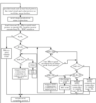
On the paper, SOC management of Wind/ Photovoltaic Micro-grid power generation is designed combined with Micro-grid power production and load forecasting, SUG load forecasting, battery charge and discharge monitoring data. By combination of stage planning and on-line monitoring, preplanning is used innovatively for battery charge and discharge according to power production prediction, electricity storage required of the battery for each period is given out in terms of SOC. SOC forecast of each sampling period is done, then forecast error correction is performed according to measured actual value of SOC, charge and discharge control is realized, overcharge or over-discharge is avoided, efficient use of battery is achieved.Specific initial value preset for SOC control against overcharge and over-discharge is reference to the total amount during previous period, when the discharge is less than 20%, cut-off signal of discharge is started. When SOC is higher than 80%, SUG connection signal is started to discharge. On the other hand, Micro-grid power production and dynamic load change also put forward corresponding requirements to the power flexible input and output of the energy storage system, battery can be connected to the DC bus by bi-direction DC/DC converter [12]. Bidirectional power flow between the SUG and Micro-grid is realized.
4.3. SUG Connection Controller Design under Load Reliable Operation
PF=PL
load forecast PL, Micro-grid total
power to predict PF, battery power
monitoring PE, SOC monitor
the total wind and solar power as well the stage before
Figure 4. Energy Storage System Intelligent Control Strategy Schematic
given out. The overall design schematic diagram of intelligent control strategy is as shown in Figure 4; prediction error at each moment is adjusted according to pre-period prediction and monitor actual value of the Wind/Photovoltaic power production and load demand, and Wind/Photovoltaic power output and load power demand are forecasted for the next period. Then take Wind/Photovoltaic power production and load demand prediction value as a control basis, combined with the current battery SOC, the SUG connection control signal is given out. Meanwhile, according to the SUG load distribution and quantity of Micro-grid load demand and power production during SUG load peak period within the future 24 hours, the amount of energy needed to be stored in advance is planned during SUG valley load period.
5. Information Fusion Intelligent Control Algorithm Validation
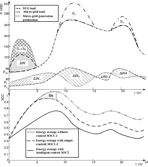
Intelligent algorithm is combined with forecasting on SUG load, Micro-grid power production, the battery SOC and other information as well, giving charge and discharge control signals and the SUG connection control signal all along, ensure Micro-grid load supplied friendly from SUG connection when needed. The control algorithm can be verified by analyzing in Figure 5.
Figure 5. Operation Curve Contrasting of Batteries Storage
and load demand during the four periods are achieved. W1,W2, W3, W4, ΣΔW are achieved, there are 186kWh, -264kWh, 46KWh, -106kWh, so ΣΔW is -138kWh. Where Micro-grid power production has surplus, the energy is positive, once the Micro-grid power production is not enough, the energy is shown negative.
5.1. Energy Storage System Charge and Discharge without Control
Lower part in Figure 5 shows a SOC curve of energy storage system under different working ways within Micro-grid. In the Figure, SOC1 curve is corresponding to random battery charge and discharge mode without special control, whose behavior depends entirely on the Micro-grid power production and load supply demand. If Micro-grid power production has surplus, battery is charged and stored energy. On the contrary, battery storage is used on priority to supplement and maintain normal operation of Micro-grid load. Once the battery runs out, the Micro-grid load is supplied by connecting to the SUG. It is seen from the SOC1 curve, the battery SOC is 0.33 at 0:00, Micro-grid power generation is surplus from 0:00 to 8:30, the battery has been in charge state during this period, SOC increases from 0.33 to 0.567. After 8:30, due to the insufficient power production, energy storage system discharges to supply Micro-grid load operation, SOC drops to 0.223 at 15:30. Micro-grid power production surplus occurs from 15:30 to 18:08, energy storage system is recharged, SOC is up to 0.281. After 18:08, Micro-grid power production is faced shortage and energy storage system must be discharged to supply Micro-grid load again, till to 23:06, the SOC drops to 0.141, less than 20%, an over-discharge phenomenon is shown obviously. If the state continues, the battery life would be affected.In addition, if the energy storage has been exhausted in this process, Micro-grid power production is not enough to supply on Micro-grid load as well, and that occurs just at load peak period of SUG and Micro-grid, the Micro-grid load superimposed externally would undoubtedly enhance the supply pressure on SUG, so load shifting is needed urgently.
5.2. Simple Storage Control Mode Considering Storage Protection
SOC2 curve in Figure 5 is a simple working mode with overcharge and over-discharge control. The Micro-grid power production has surplus, energy storage systems is started to charge, once storage is more than 80 percent, SUG connection is touched to discharge. If Wind/Photovoltaic power production is insufficient, Micro-grid is connected to SUG to supplement power. On the simple control, no stage plan on energy storage systems is designed in advance. Due to SOC has been less than 80% within 24 hours, the energy storage system discharge signal is not be triggered. In addition, two-stage Micro-grid power production are insufficient during 10:00 to 12:00 and 19:00 to 21:00, which cause SUG load peak increased respectively from 258kW to 320kW (10:00 to 12:00), and from 238.5kW to 270kW (19:00 to 21:00). This is equivalent that Micro-grid load supply shortage be superimposed directly to the SUG (Figure 5. S1, S2), increasing the SUG load peak supply pressure.
controlled effectively. It is also seen that the energy storage system supplements to supply power to grid load operation during the two periods (SOC decreased), so ensure Micro-grid on-line power supply requirements during SUG load peak period. Energy storage system is charged from SUG during valley hours, equivalent to enhance the valley load of SUG, peak load shifting is realized.
5.4. Economic Benefit Evaluation on System Operation
Combined with multi-information monitoring and prediction, future Micro-grid energy supply demand of load is stored in advance during SUG valley periods (138kWh, ΔSOC is 0.191), which is shown as in SOC3 curve in Figure 5, meeting the demand of future Micro-grid load operation during SUG load peak period. Taking one region sharing price as a reference at JiangSu Province China (the standard price ¥0.5583 /kWh, peak segment 8: 00-21: 00 AM, valley segment 21: 01 PM- 8:00 AM of the next day, the standard price of ¥0.3583/kWh), excluding special electricity supply, at least ¥27.6 every day can be saved with intelligent controller. In addition, SOC changes from 0.33 to 0.758 in the whole process, not showing overcharge and over-discharge, the battery has been maintained in a healthy state. Therefore, a reasonable amount set of electrical energy stored in advance by intelligent controller is also very important.
6. Conclusion
Taking new energy power generation as the theme, according to the SUG load changes and Micro-grid load changes, considering the working characteristics and energy management of energy storage system, and with the goal of alleviating the peak power supply pressure of the SUG, the overall control objective is devised and Wind/Photovoltaic/storage power system topology is researched and designed based on the relationship analysis of Micro-grid generation production and load demand. The intelligent control algorithms of energy storage system are designed under the overall consideration of the UG load and Micro-grid load, Wind/Photovoltaic generation output, electricity peak distribution. Energy storage plan is done ahead of schedule, saving enough spare capacity at the valley as far as possible. The multi-information fusion is adopted with close combination of multi-point dynamic monitoring data. Active control is realized from the demand side and the economic benefit evaluation is done.
System debugging analysis shows that the controller can trigger UG connection flexibly according to the Micro-grid output and load demand and energy storage SOC. Reliable operation of the Micro-grid load is achieved finally. Partial peak load is moved to valley segment, ease the supply pressure of the SUG during peak load period, the public grid reserve capacity can be reduced effectively, Micro-grid operating costs is reduced as well. On the other hand, bidirectional DC/DC converter is introduced in the Wind/Photovoltaic/storage complementary system, reducing the number of the electronic components and the equipment volume. The overall design of the system has the application of promotional value.
Acknowledgements
This work is a part of the National Research Programs of China (No. 51377047, No. 51407097) and the Jiangsu Provincial Department of Education University Natural Foundation of China (No.15KJB470014, No.16KJB470014). The authors would like to thank for the supports from both the Ministry of Science and Technology and National Natural Science Foundation of China.
References
[1] Nirmal-Kumar C. Nair, Lei Jing. Power quality analysis for building integrated PV and micro wind turbine in New Zealand. Energy and Buildings. 2013; 58: 302-309.
[2] Yuanxiong Guo, Miao Pan, Yuguang Fang. Optimal Power Management of Residential Customers in the Smart Grid. IEEE Transactions on Parallel and Distributed Systems. 2012; 23(9): 1593-1606. [3] SM Shaahid. Review of research on autonomous wind farms and solar parks and their feasibility for
commercial loads in hot regions. Renewable and Sustainable Energy Reviews. 2011;15: 3877-3887. [4] Yao Low Wen, Prayun Wirun Al, Abdul Aziz, et al. Battery State-of-Charge Estimation with Extended
Electronics and Control). 2015; 13(2):401-412.
[5] JK Kaldellis, D Zafirakis. Optimum sizing of stand-alone wind-photovoltaic hybrid systems for representative wind and solar potential cases of the Greek territory. Journal of Wind Engineering and Industrial Aerodynamics. 2012; 107: 169-178.
[6] MS Carmeli, P Guidetti, M Mancini, et al. Hybrid distributed generation system for a rural village in Africa. 3rd Renewable Power Generation Conference. Milan, Italy. 2014: 1-6.
[7] M Bashir, J Sadeh. Optimal Sizing of Hybrid Wind/Photovoltaic/Battery Considering the Uncertainty of Wind and Photovoltaic Power Using Monte Carlo. IEEE 11th International Conference on Environment and Electrical Engineering. Venice, Italy.2012: 1081-1086.
[8] Chen Dingyue, Li Xia Chen, Lihao Zhang, et al.. Basal Study on Power Control Strategy for Fuel Cell/Battery Hybrid Vehicle. TELKOMNIKA (Telecommunication Computing Electronics and Control). 2015; 13(2): 421-431.
[9] Seung Tae Cha, Haoran Zhao, et al.Coordinated control scheme of battery energy storage system (BESS) and distributed generations (DGs) for electric distribution grid operation. IEEE 38th Annual Conference on Industrial Electronics Society. Montreal. 2012: 4758-4764.
[10] Hamidreza Ghoddami, Mohammad B Delghavi, Amirnaser Yazdani. An integrated wind-photovoltaic-battery system with reduced power-electronic interface and fast control for grid-tied and off-grid applications. Renewable Energy. 2012; 45: 128-137.
[11] Sharad W Mohod, Mohan V Aware. A STATCOM-Control Scheme for Grid Connected Wind Energy System for Power Quality Improvement. IEEE Systems Journal. 2010; 4(3): 346-352.