DESIGN OPTIMIZATION OF A BOILER FURNACE
AZRUL AFFENDI ATAN
i
“I hereby verify that I have read this report and I find it sufficient in term of quality and scope to be awarded with the Bachelor Degree in Mechanical Engineering “
Signature : ………
Supervisor Name : ………
ii
DESIGN OPTIMIZATION OF A BOILER FURNACE
AZRUL AFFENDI ATAN
This report is submitted to Faculty of Mechanical Engineering in partial fulfill of the requirement of the award of Bachelor’s Degree of Mechanical Engineering
(Thermal-fluid)
Faculty of Mechanical Engineering
UNIVERSITI TEKNIKAL MALAYSIA MELAKA
iii
“I hereby to declare that the work is my own except for summaries and quotations which have been fully acknowledge”
Signature : ……….
iv
DEDICATION
To him who is our source of grace, our source of commitment, and our source of knowledge,
And,
v
ACKNOWLEDGMENT
All praises to the Almighty Allah, for giving me the strength, patience and guidance throughout the process of completing this investigation. I am grateful to have the morally and physically support from many people throughout completing this study. For this opportunity, I would love to thank whose are either directly or indirectly involved during the process of this research is conducted.
Most important, I would like to express my very special gratitude and appreciation to my supervisor, Mdm. Ernie bte Mat Tokit for her valuable suggestion, comments and advice in every stage of this project. All the discussion makes me understand every detailed in this biomass boiler analysis. My token of appreciation also goes to all the lecturers from Faculty of Mechanical Engineering especially from Mechanical Department for being very nice and making this study easier to be completed.
vi
ABSTRACT
vii
ABSTRAK
viii
TABLE OF CONTENTS
CHAPTER TITLE PAGE
DECLARATION iii
DEDICATION iv
ACKNOWLEDGEMENT v
ABSTRACT vi
ABSTRAK vii
TABLE OF CONTENTS vii
LIST OF TABLE xi
LIST OF FIGURE xii
LIST OF SYMBOL xiii
ix
CHAPTER 1 INTRODUCTION
1.1 INTRODUCTION 2
1.2 OBJECTIVES 3
1.3 WORK SCOPES 3
1.4 PROBLEMS STATEMENT 4
1.5 SIGNIFICANT OF STUDY 4
CHAPTER 2 LITERATURE REVIEW
2.1 COMPUTATIONAL FLUID 5
DYNAMICS (CFD)
2.2 BIOMASS STEAM BOILER 8
(CONTROL VOLUME)
2.3 OPERATING SYSTEM 11
2.4 AIR FLOW PATH DESIGN 12
2.5 TURBULENT MODELLING IN 14
FLUENT
2.5.1 THE SPLALART ALLMARAS 14
TURBULENT MODEL
2.5.2 THE STANDARD k- ɛ 15
TURBULENCE MODEL
2.5.3 RENORMALIZATION GROUP 15
(RNG) k- ɛ MODEL
2.5.4 REALIZABLE k- ɛ (RKE) MODEL 15
2.5.5 LARGE EDDY SIMULATION (LES) 16
x
CHAPTER 3 METHODOLOGY
3.1. CONTROL VOLUME MODELING 20
3.2. RAW DRAWING EXTRACTION 22
3.3. SOLIDWORK 3D MODELING 24
3.4. MESHING 29
3.5. FLUENT 34
3.6. DESIGN MODIFICATION 36
3.6.1. CASE STUDY 1 –
ACTUAL DESIGN ANALYSIS 36
3.6.2. CASE STUDY 2 – MODIFICATION OF
FLUE DUCT 37
3.6.3. CASE STUDY 3 – MODIFICATION OF SECONDARY INLET
POSITION (DESIGN 1) 39
3.6.4. CASE STUDY 4 – MODIFICATION OF SECONDARY INLET
xi
CHAPTER 4 RESULT
4.
4.1. RESULTS OF CASE STUDY 1 –
SIMULATION FOR ACTUAL DESIGN 45
4.1.1. FLOW PENETRATION
IN FIRE TUBES BOILER 45
4.1.2. TURBULENCE ANALYSIS 46
4.1.3. FLOW TRACKING ANALYSIS 48
4.2. RESULTS OF CASE STUDY 2 – SIMULATION FOR FLUE DUCT
MODIFICATION 53
4.2.1. FLOW PENETRATION IN
FIRE TUBES BOILER 53
4.2.2. TURBULENCE ANALYSIS 55
4.2.3. FLOW TRACKING ANALYSIS 56
4.3. RESULTS OF CASE STUDY 3 – SIMULATION FOR MODIFICATION OF SECONDARY AIR INLET
POSITION (DESIGN 1) 58
4.3.1. TURBULENCE ANALYSIS 59
4.3.2. FLOW TRACKING ANALYSIS 60
4.4. RESULTS OF CASE STUDY 4 –
SIMULATION FOR MODIFICATION OF SECONDARY AIR INLET POSITION
(DESIGN 2) 61
4.4.1. TURBULENCE ANALYSIS 62
4.4.2. FLOW TRACKING ANALYSIS 63
4.5. ERROR AND RECOMMENDATION 64
xii
CHAPTER 5 CONCLUSION & RECOMMENDATION 66
REFERENCES 67
xiii
LIST OF TABLE
NO. TITLE PAGE
xiv
LIST OF FIGURES
NO. TITLE PAGE
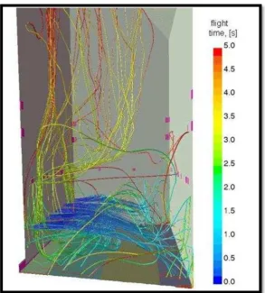
2.1.1 Light time of particles trajectories 6
2.1.2 Flow chart of CFD simulation 7
2.2.1 Biomass boiler construction 8
2.2.2 Particulate distribution simulation 9
2.2.3 Boiler System Components 10
2.4.1 Flue duct design 12
2.4.2 Particles trajectories 13
3.2.1 AUTOCAD Drawing 22
3.3.1 3D drawing using solidwork 23
3.3.2 Left view of the control volume 24
3.3.3 Front view of the control volume 24
3.3.4 Transparent view inside the furnace 25 3.3.5 Transparent view of fire tubes inlet 26 3.3.6 Extruded cutting process of the fire tubes 26
3.3.7 Position of inlet secondary air 27
3.3.8 Primary fan construction 27
3.4.1 Meshing grid construction 29
3.4.2 Meshing around critical area 30
3.7.1 Predicted temperature distribution in mid plane view 32
4.1 Reference planes 44
4.1.1.1 Velocity vectors at fire tubes section 46 4.1.2.1 Contour of turbulent intensity viewed from plane 1 47 4.1.2.2 Contours of turbulent viscosity viewed from plane 1 48
xv
4.1.3.2 Particles path line after 1000 steps 50 4.1.3.3 Graph of particle ID versus travelling time for 1000 steps 50 4.2.1.1 Comparison of velocity magnitude 53
4.2.1.2 Plant layout 54
4.2.2.1 Result comparison between actual and
modified turbulent intensity 55
4.2.2.2 Result comparison between actual and modified
turbulent viscosity 55
4.2.3.1 Pathlines colored by partcle ID 56
4.2.3.2 Graph related to particle trajectories 57 4.3.1.1 Turbulent viscosity for actual and modified design 59 4.3.1.2 Turbulent intensity for actual and modified design 59 4.3.2.1 Pathlines colored by travelling time for case study 3 60 4.3.2.2 Graph of particles trajectories for case study 3 60 4.4.1.1 Turbulent viscosity comparison for case study 4 62 4.4.1.2 Turbulent intensity comparison for case study 4 62
4.4.2.1 Flow tracking analysis 63
xvi
LIST OF SYMBOL
2D = 2 Dimension
3D = 3 Dimension
CFD = Computational Fluid Dynamics CDM = Clean Development Mechanism
SGS = Sub-grid scale
LES = Large Eddy Simulation SSTKW = Shear Stress Transport k-ω SKW = Standard k-ω
ε = Epsilon
xvii
LIST OF APPENDICES
NO. TITLE PAGE
A Biomass boiler plant blue print 70
B System component 71
C Plant construction 72
D 3D Control volume drawing 73
E Carta alir pengendalian psm 74
F Technical data 75
G Hardware and software specification 79
1
CHAPTER 1
INTRODUCTION
1.1 INTRODUCTION
Boiler is a steam producing system that involve of heating raw water into a high energy of steam. The manipulation of steam properties produced are varies in wide range of application and industry. High in temperature, pressure and velocity has made steam as a main medium of energy transportation since decades ago. With modernization and continuous technology upgrading, the ability of boiler seems to move along and become more important.
2
The introduction of biomass fuel boiler from years ago seems to gain more acceptances in industry. This is due to the manipulation of solid waste which giving much more benefit in aspect of cost cutting. With continuous research and ability upgrading, little by little this type of boiler is replacing the use of oil based fuel boiler. Thanks to the current market price of oil that is high and sometimes undetermined. Moreover, the high efficiency of biomass steam boiler strengthens the reason for having a place in industry.
Since solid wastes are continuously produced and need proper management, the existence of biomass boiler seems to have solves or at least reduces responsibility carried by industries such as palm oil and wood manufacturing industry. Here the useable chain of solid waste were created where biomass steam boiler optimize the use of natural source until the maximum. Moreover, ashes produced from complete combustion in the boiler furnace recently rising in request especially from agriculture industries.
This project was inspired from my industrial training experience in biomass steam plant at ENCO DANSTOKER (M) SDN BHD. Empty fruit bunch is the main fuel used and at certain time being supported by palm kernel shell, wood chips and mesocarp fiber. The whole system applied in the plant is so interesting where water treatment, fuel processing, air cycle, combustion and steam transportation systems were combined using latest technology.
3
1.2 OBJECTIVES
1. To optimize the current boiler design by modifying the flue duct design and secondary air inlet positions.
1.3 WORK SCOPES
1. To run a simulation of flow in biomass boiler furnace using computational fluid dynamics (CFD) software.
2. To study the effects of current design towards air flow pattern.
3. To make comparison and optimization of fuel scattering by modifying flue duct design.
4. To make comparison and optimization of turbulence and fuel trajectories relative with time by modifying secondary air inlet positions.
4
1.4 PROBLEMS STATEMENT
During normal operation, Enco Danstoker (M) sdn bhd’s biomass boiler facing several problems related to its system. Flow distribution at the outlet of the furnace (inlet of fire tubes) is not evenly distributed. This will result in right side of the fire tubes inlet clogging faster than the other side. Too much ash particulate emission is obtained released from the system which indicates a problem in flow pattern inside the furnace and combustion level.
1.5 SIGNIFICANT OF STUDY
5
CHAPTER 2
LITERATURE REVIEW
2.1 COMPUTATIONAL FLUID DYNAMICS (CFD) IN FLOW ANALYSIS
The equations for fluids thermal are quite complex and can be difficult to solve, especially if the geometry of a problem is complex. By making use of computers as a computational tool, we can solve these equations in nearly any arbitrary situation. The computational method allows us to get results quickly (a matter of minutes to hours depending on the complexity) and visually close to reality. These results can be used to guide experiments and even as a substitute for preliminary testing in situations where building prototypes might be prohibitively expensive.
6
[image:24.595.171.465.192.518.2]Current CFD software compatibility allows integrated with other software such as Solidwork. This will be taken as advantages where degree of similarity of the analysis’s system can be achieved as close as possible with the true system. The use of Soliwork software will make drawing process of control volume easier, faster and more accurate.
Figure 2.1.1: Light time of particles trajectories (Source: FLUENT.com)