A NEW PROCEDURE FOR HIGH FREQUENCY ELECTRONIC BALLAST DESIGN
HO TZE YUAN
“I hereby declared that I have read through this report and found that it has comply the partial fulfillment for awarding the degree of Bachelor of Electrical Engineering (Power Electronic and Drives)”
Signature : ……….
Supervisor’s Name : EN. ALIAS BIN KHAMIS
A NEW PROCEDURE FOR HIGH FREQUENCY ELECTRONIC BALLAST DESIGN
HO TZE YUAN
This Report Is Submitted In Partial Fulfillment Of Requirements For The Degree Of Bachelor In Electrical Engineering (Power Electronic and Drives)
Fakulti Kejuruteraan Elektrik Universiti Teknikal Malaysia Melaka
“I hereby declared that this report is a result of my own work except for the excerpts that have been cited clearly in the references.”
Signature : ……….
Name : HO TZE YUAN
iii
ACKNOWLEDGEMENT
ABSTRACT
v
ABSTRAK
CONTENTS
CHAPTER TITLE PAGE
ACKNOWLEDGEMENT iii
ABSTRACT iv
ABSTRAK v
CONTENTS vi
LIST OF TABLES viii
LIST OF FIGURES ix
LIST OF ABBREVIATION xii
LIST OF APPENDIX xiii
I INTRODUCTION
1.1 Problem Statements 5
1.2 Project Objectives 5
1.3 Problem Scopes 5
1.4 Thesis Outline 6
1.5 Project Planning 8
II LITERATURE REVIEW
2.1 Conventional Ballast 10
2.2 Problems Caused By Conventional Ballast 11
2.3 Electronic Alternatives 12
2.4 Electronic Ballast 12
2.5 Full Bridge Rectifier 13
2.6 Half Bridge Inverter 16
2.7 Filter 19
vii
III METHODOLOGY
3.1 Flow Chart 21
3.2 Fourier Analysis 23
3.3 OrCAD 26
3.4 Fluke Quality Analyzer 31
3.4.1 Measuring Lighting Load 31 3.4.1.1 Inrush current 31 3.4.1.2 Power And Power Factor 33 3.4.1.3 Total Harmonic Distortion 35
3.5 Illuminometer 36
3.5.1 Features 37
3.5.2 Operating Instructions 38
3.5.2.1 Preparations For Measurement 38 3.5.2.2 How To Make Measurements 38
IV RESULTS AND DISCUSSIONS
4.1 Calculation And Simulation 42
4.1.1 Magnetic Ballast 42
4.1.2 Electronic Ballast 49
4.1.2.1 Fourier Analysis 49 4.1.2.2 Transient Analysis 50 4.1.2.3 Steady State Analysis 51
4.2 Hardware And Analysis 55
4.2.1 Circuit Operation 55
4.2.2 Magnetic Ballast 65
4.2.3 Electronic Ballast 67
4.3 Summary 70
V CONCLUSION
5.1 Recommendation 73
REFERENCES 75
LIST OF TABLES
NO TITLE PAGE
1.1 Gantt chart 8
3.2 Recommended average illuminance levels 40
3.3 Adequate light levels for working area 41
4.1 Electronic ballast components 64
4.2 Comparison between magnetic ballast and electronic ballast 70 5.1 Comparison between electronic ballast and conventional ballast 72
ix
LIST OF FIGURES
NO TITLE PAGE
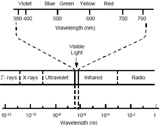
1.1 Electromagnetic spectrum 1
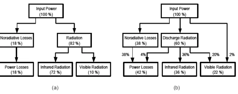
1.2 (a) Energy distribution of an incandescent lamp. (b) Energy distribution of a fluorescent lamp.
2
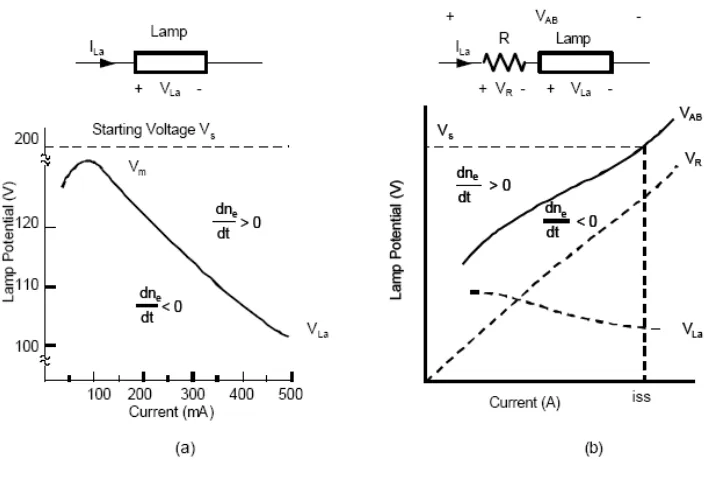
1.3 (a) Discharge potential drop versus current. (b) The effect of series resistance in stabilizing lamp current.
3
1.4 Scope of constructing electronic ballast 5
2.1 Simple conventional lamp ballast 10
2.2 Electronic ballast block diagram 13
2.3 Full bridge rectifier 13
2.4 Positive half-cycle rectification 14
2.5 Negative half-cycle rectification 14
2.6 AC, half-wave and full wave rectified signals 14
2.7 Buffer capacitor 15
2.8 Half Bridge Inverter 16
2.9 Center-tapped half bridge inverter 17
2.10 Conduction Pattern for inverter 17
2.11 Circuit topology of half bridge series resonant inverter 18
2.12 Lowpass filter 19
3.1 Flow chart 21
3.2 Fundamental and harmonic component 23
3.3 Square wave 24
3.4 Harmonic spectrum 25
3.5 Capture CIS 26
3.6 Schematic diagram 26
3.10 Fourier analysis 28
3.11 Total harmonic distortion 29
3.12 Fluke quality analyzer 30
3.13 Lighting load connection 32
3.14 Inrush current menu 33
3.15 Power and power factor measurement connection 34
3.16 Power menu 34
3.17 Total harmonic distortion measurement connection 35
3.18 Total harmonic menu 36
3.19 Illuminator 36
3.20 Illuminator designations 37
4.1 Resistive lamp model 42
4.2 Magnetic ballast simplified model 43
4.3 Impedance diagram 43
4.4 Simulation model of the magnetic ballast 44
4.5 Simulation result of output voltage waveform for the magnetic ballast
46
4.6 Simulation result of input voltage, output voltage and current output waveform for the magnetic ballast
47
4.7 Simulation result of current waveform at load for the magnetic ballast
48
4.8 Output voltage of half bridge rectifier 49
4.9 Resonant lamp output stage during transient 50
4.10 Resonant lamp output stage during steady state 51 4.11 Resonant lamp output stage during steady state simplified
model
52
4.12 Simulation model of the electronic ballast 53
4.13 Simulation result of lamp voltage 54
4.14 Simulation result of lamp current 54
4.15 Schematic of electronic ballast 55
xi
4.17 Source voltage analyzed using Fluke software 57
4.18 Bridge rectifier voltage captured by Fluke 57
4.19 Bridge rectifier voltage analyzed using Fluke software 58
4.20 Capacitor voltage captured by Fluke 58
4.21 Capacitor voltage analyzed using Fluke software 59 4.22 Half bridge inverter voltage captured by Fluke 59 4.23 Half bridge inverter voltage analyzed using Fluke software 60 4.24 Half bridge inverter voltage captured by Fluke 60 4.25 Half bridge inverter voltage analyzed using Fluke software 61
4.26 Choke voltage captured by Fluke 61
4.27 Choke voltage analyzed using Fluke software 62
4.28 Lamp voltage captured by Fluke 62
4.29 Lamp voltage analyzed using Fluke software 63
4.30 Electronic ballast 63
4.31 Front view of electronic ballast 64
4.32 PCB layout 65
4.33 Voltage and current for magnetic ballast 66
4.34 Power factor for magnetic ballast 66
4.35 Total harmonic distortion voltage for magnetic ballast 67 4.36 Total harmonic distortion current for magnetic ballast 67 4.37 Curve of fluorescent lamp efficacy versus lamp operating
frequency
68
4.38 Voltage and current for electronic ballast 69
4.39 Power factor for electronic ballast 69
4.40 Total harmonic distortion voltage for electronic ballast 69 4.41 Total harmonic distortion current for electronic ballast 70
5.1 Basic construction of electronic ballast 71
LIST OF ABBREVATION
AC - Alternating Current DC - Direct Current
HPS - High Pressure Sodium LPS - Low Pressure Sodium THD - Total Harmonic Distortion PCB - Printed Circuit Board EM - Electromagnetic
DIAC - Diode for Alternating Current
MOSFET - Metal–Oxide–Semiconductor Field-Effect Transistor IC Integrated Circuit
SIP System In Package
xiii
LIST OF APPENDIX
NO TITLE PAGE
INTRODUCTION
[image:16.595.184.454.491.704.2]Light is defined as visually evaluated radiant energy, which stimulates man’s eyes and enables him to see. Man has always sought to counter the influence of the darkness by creating artificial light. The discovery of electric power and the possibility of transmitting it in a simple manner facilitated the development of modern lamps. Today there are nearly 6,000 different lamps being manufactured, most of which can be divided into six categories: incandescent, fluorescent, mercury vapor, metal halide, high-pressure sodium (HPS) and low-pressure sodium (LPS). Except for incandescent lamps, all of these light sources can be termed as gas discharge lamps.
The major characteristics to be considered when choosing a lamp are its luminous efficacy, life, lumen depreciation and color rendering. Luminous efficacy is the measure of the lamp’s ability to convert input electric power, in watts, into output luminous flux, in lumens, and is measured in lumens per watt (lm/w). The luminous flux of a light source is the electromagnetic radiation within the visible part of the electromagnetic spectrum multiplied by the sensitivity of man’s eyes to that part of the light from the source. The visible portion of the spectrum covers the wavelength range from approximately 380 nm to 780 nm as shown in Figure 1.1. The life of a lamp is the number of hours it takes for approximately 50% of a large group of lamps of the same kind to fail. Failure means that the lamp will no longer light or that light output has dropped to a specific percentage value. Lumen depreciation during life is a characteristic of all lamps. This is a process of lamp aging, an important consideration in lighting design. Finally, there is the matter of color rendering. The lamp types do not provide the same nominal “white.” Their difference in spectral distribution can produce two effects within a lighted space. Some of the colors of objects within that space can appear unnatural or faded – reds can appear brown, violets nearly black, etc. Second, the entire space may “feel” warm or cool. For example, a mercury lamp, lacking in reds and oranges, makes a space seem cool, whereas an incandescent lamp, with deficiencies in the blue and violets, makes a space feels warm.
As a result, gas discharge lamps cannot be directly connected to a voltage source. Certain impedance must be placed between the discharge lamp and the voltage source as a means to limit lamp current. For example, Figure 1.3(b) shows the effect of series resistance in stabilizing lamp current. The dotted lines and show the voltage potential across the discharge and resistor, respectively, and the solid line VAB shows the potential across the pair in series.
Upon application of a starting voltage to the lamp-resistor system and establishment of ionization, the operating point (i,v) is in the domain of positive dne/dt, increasing the lamp current until it reaches the point (iss,Vs). A further
increase in current would move the operating point into the region of negative dne/dt, forcing the current back to iss. The resistor R helps to establish the stable operating point of the discharge lamp and acts as the ballast.
Obviously, the resistive ballast incurs large power loss and significantly reduces the system efficiency. Fortunately, most discharge lamps are operated in alternating-current (AC) circuits so that inductive or capacitive impedance can be used to provide current limitation. AC operation also balances the wearing of two electrodes and maintains a longer lamp life. The inductor ballast represents the conventional ballasting approaches, and is known as magnetic ballasts.[1]
1. Provide a start up voltage across the end electrodes of the lamp. 2. Construct a self-oscillating gate driver.
3. Maintain a constant current when lamp is operating in steady-state. 4. Assure that the circuit will remain stable.
1.2 Project objectives
These are the objectives of this project:
1. Study the characteristic of high frequency electronic ballast. 2. Design high frequency electronic ballast.
3. Develop the circuit of high frequency electronic ballast.
4. Comparison between electronic ballast with conventional ballast.
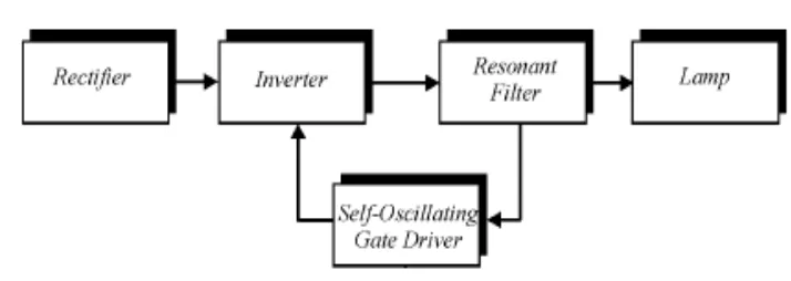
[image:20.595.137.494.495.622.2]1.3 Project scopes
Figure 1.4: Scope of constructing electronic ballast
power to DC power. A self-oscillating gate driver is used to switch on and off complimentary of transistors to produce a high frequency square wave of inverter output. Then, the square wave is gone through the low-pass filter to eliminate the undesired harmonic components. Finally, a comparison between electronic ballast and conventional ballast will be done by doing circuit analysis.
1.4 Thesis outline
In this project, I would like to design electronic ballast to drive a 36W fluorescent lamp. In this report, I will discuss it in detail in five sections. There are introduction, literature review, methodology, results and discussions, and conclusion.
In chapter one (introduction), I discussed about the major characteristics to be considered when choosing a lamp. There are more advantages of gas discharge lamps over incandescent lamps but they require a ballast to run with them because gas discharge lamps have negative incremental impedance. The problem statement, project objectives, scope and thesis outline are also included in this chapter.
In chapter two (literature review), a comparison between the conventional and electronic ballast is made. The comparison is made by discussing the operation of conventional ballast and the problems caused by conventional ballast. Then electronic alternatives are provided to encounter the problems. Later, each part of the electronic ballast is discussed in detail. The full bridge rectifier, half bridge inverter, and filter is discussed separately in their contribution to the functional of electronic ballast.
obtained during simulation. Finally, I proceed to the hardware part. Here all the obtained results are gathered. Finally, analysis is done according to the results.
1.5 Project planning
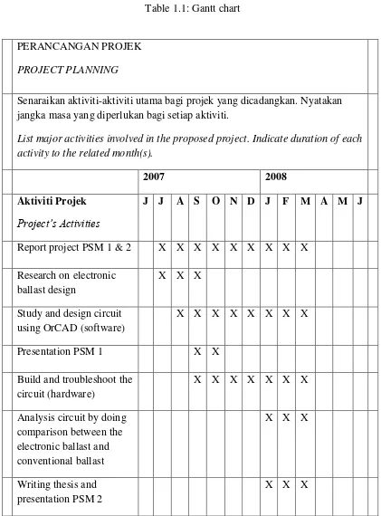
Table 1.1: Gantt chart
PERANCANGAN PROJEK PROJECT PLANNING
Senaraikan aktiviti-aktiviti utama bagi projek yang dicadangkan. Nyatakan jangka masa yang diperlukan bagi setiap aktiviti.
List major activities involved in the proposed project. Indicate duration of each activity to the related month(s).
2007 2008
Aktiviti Projek Project’s Activities
J J A S O N D J F M A M J
Report project PSM 1 & 2 X X X X X X X X X Research on electronic
ballast design
X X X
Study and design circuit using OrCAD (software)
X X X X X X X X
Presentation PSM 1 X X
Build and troubleshoot the circuit (hardware)
X X X X X X X
Analysis circuit by doing comparison between the electronic ballast and conventional ballast
X X X
Writing thesis and presentation PSM 2
X X X