ii
DECLARATION
“I hereby, declare this thesis is result of my own research except as cited in the references”
Signature : ……….
Author’s Name : Lim Swee Meng
iii
ACKNOWLEDGEMENT
iv
ABSTRAK
Kajian ini menumpu kepada penyelidikan kesan permukaan kawalan (rudder dan ailerons) bagi sebuah model kapal terbang terhadap pekali side force, CY, pekali momen yawing, Cn, dan pekali momen rolling, Cl, dengan menggunakan terowong angin subsonik yang tertutup. Kesan terhadap model dengan mengubah sudut gelincir, sudut rudder dan sudut ailerons akan diuji dengan menggunakan terowong angin subsonik adalah untuk mendapatkan nilai pekali side force, CY, pekali momen yawing, Cn, dan pekali momen rolling, Cl. Seperti yang dijangkakan, perubahan sudut rudder adalah berkesan dalam mengawal pekali moment yawing. Perubahan sudut rudder adalah berkadar secara tidak langsung dengan pekali momen yawing apabila perubahan sudut rudder meningkat pekali momen yawing akan berkurang. Kepututsan eksperiment menunjukan bahawa perubahan sudut rudder adalah berkesan dari -5º sehingga -10º untuk mengawal pekali momen yawing. Selain daripada itu, keputusan eksperiment juga menunjukan bahawa perubahan sudut ailerons adalah berkesan dalam mengawal pekali momen rolling dan pekali momen yawing. Kesan langsung bagi perubahan sudut ailerons adalah dalam mengawal
pekali momen rolling. Perubahan sudut ailerons berkadar secara langsung dengan pekali momen rolling. Apabila perubahan sudut ailerons meningkat pekali momen rolling juga akan meningkat. Keputusan eksperiment menunjukan bahawa perubahan
v
ABSTRACT
vi
TABLE OF CONTENTS
CHAPTER TOPIC PAGE
DECLARATION ii
ACKNOWLEDGEMENT iii
ABSTRAK iv
ABSTRACT v
TABLE OF CONTENTS vi
LIST OF FIGURES ix
LIST OF TABLES xii
LIST OF SYMBOLS xiii
LIST OF APPENDICES xv
CHAPTER 1.0 INTRODUCTION 1
1.1 Background Study 1
1.2 Problem Statement 2
1.3 Objectives 2
1.4 Scope 2
CHAPTER 2.0 LITERATURE REVIEW 3
2.1 Basic Aerodynamics of An Aircraft 3
2.2 Aerodynamics Studies for effect of control surfaces on An Aircraft 5
vii
CHAPTER TOPIC PAGE
2.3.1 Yaw Moment 7
2.3.2 Rudder Considerations 9
2.3.3 Roll Moment 10
2.3.4 Dihedral Effect, Clβ 11
2.4 Studies On Wind Tunnel 17
2.4.1 Principal of Lift and Drag 18
2.4.2 Skin Friction and Pressure Drags 19
2.4.3 Force and Moment Data 21
2.4.4 Pressure Data 22
2.4.5 Dynamic Data 22
2.4.6 Endurance Data 23
CHAPTER 3.0 METHODOLOGY 24
3.1 Data mining and Experimental Investigation 24
3.2 Wind Tunnel Test Specifications 25
3.3 Analysis of Wind Tunnel Test Data 26
3.4 Wind Tunnel Test Design 28
3.4.1 Geometrical Characteristics of the Model 28
3.4.2 Model and Test Conditions 29
3.4.3 Directional and Rolling Test 30
3.5 Wind Tunnel Test Procedures 34
3.6 Analysis 36
CHAPTER 4.0 RESULTS AND DISCUSSION 40
4.1 Rudder Deflection 41
4.1.1 Side Force Coefficient 41
4.1.2 Yawing Moment Coefficient 45
4.1.3 Rolling Moment Coefficient 50
4.2 Ailerons Deflection (right wing as reference) 55
4.2.1 Side Force Coefficient 55
viii
CHAPTER TOPIC PAGE
4.2.3 Rolling Moment Coefficient 65
4.3 Error 71
CHAPTER 5.0 CONCLUSION AND RECOMMENDATIONS 72
5.1 Conclusion 72
5.2 Recommendation for future works 73
REFERENCES 74
BIBLIOGRAPHY 76
ix
LIST OF FIGURES
NO TITLE PAGE
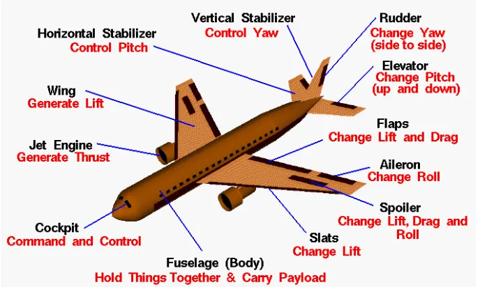
2.1 Aircraft model components 4
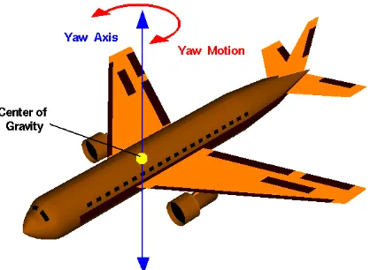
2.2 Yaw axis and yaw motion 7
2.3 Roll axis and roll motion 11
2.4 Sideslip angle, β 12
2.5` Lateral stability 13
2.6 Rolling moment varies in approximately a linear fashion with dihedral angle and sideslip 14
2.7 Sideslip induced roll 15
2.8 Propwash 16
2.9 UTM wind tunnel ground floor plan 17
2.10 Lift and Drag Forces 18
2.11 Aircraft on three-strut mount testing for force and moment data 21
x
NO TITLE PAGE
2.13 Model mounted to Wind Tunnel roof for drop test 22
2.14 Endurance test of aluminum siding 23
3.1 Methodology Flow Chart 24
3.2 Variation on Angle of Attack 31
3.3 Variation on Sideslip Angles 31
3.4 Variation on Ailerons 32
3.5 Variation on rudder 33
3.6 Mounting 35
3.7 Rudder Deflection 35
3.8 Ailerons Deflection 36
3.9 Coefficient of Side Force (Cy) versus Coefficient of Sideslip Angle (β) 37
3.10 Coefficient Side Force (Cy) versus Coefficient Rudder Deflection (δr) 37
3.11 Coefficient Yawing Moment (CN) versus Coefficient Sideslip Angle (β) 38
xi
NO TITLE PAGE
3.13 Coefficient Rolling Moment (Cl) versus Coefficient Sideslip
Angle (β) 39
3.14 Coefficient Rolling Moment (Cl) versus Coefficient Rudder
Deflection (δr) 39
4.1 Side Force Coefficient versus Yaw Angle 42
4.2 Side Force Coefficient versus Angle of Rudder 43
4.3 Yawing Moment Coefficient versus Yaw Angle 46
4.4 Yawing Moment Coefficient versus Angle of Rudder 48
4.5 Theoretical Yawing Moment Coefficient versus Angle of Rudder 48
4.6 Rolling Moment Coefficient versus Yaw Angle 51
4.7 Rolling Moment Coefficient versus Angle of Rudder 52
4.8 Side Force Coefficient versus Yaw Angle 56
4.9 Side Force Coefficient versus Angle of Ailerons 57
4.10 Yawing Moment Coefficient versus Yaw Angle 61
4.11 Yawing Moment Coefficient versus Angle of Ailerons 62
4.12 Rolling Moment Coefficient versus Yaw Angle 66
xii
LIST OF TABLES
NO TITLE PAGE
3.1 Wind Tunnel Test Data 1 27
3.2 Wind Tunnel Test Data 2 28
3.3 Ailerons Test Plan with α Sweep 32
3.4 Rudder Test Plan with α Sweep 33
3.5 Ailerons Test Plan with β Sweep 34
3.6 Rudder Test Plan with β Sweep 34
3.7 Sample of Cyversus δr data 37
3.8 Sample of CN versus δr data 38
xiii
LIST OF SYMBOLS
Concise list of symbols in order of appearance:
UAV = Unmanned Aerial Vehicles Cy = Coefficient of Side Force Cl = Coefficient of Rolling Moment CN = Coefficient of Yawing Moment β = Sideslip Angle, º
φ = Roll Angle, º Cl = Lift Coefficient Fd = Drag Force, N
ρ = Density of the Fluid, kg/m3
v = Velocity of The Object Relative to The Fluid, m/s A = Reference Area, m2
Cd = Drag Coefficient T = Torque, Nm F = Force, N L = Length, m
N = Moment, Nm
Nwb = Moment About Wing Body, Nm lvt = Vertical Tail Length, m
Dvt = Drag of Vertical Tail, N Lvt = Lift of Vertical Tail, N
αvt = Angle of Attack of Vertical Tail, º
C
Lvt = Lift Coefficient of Vertical TailSvt = Vertical Tail Area, m2
xiv
ar = Rudder Lift Curve Slope δr = Angle of Rudder, º
C
Nwb = Coefficient of Yawing Moment of Wing BodyC
Nβ = Coefficient of Yawing Moment of Sideslip AngleC
Nδr = Coefficient of Yawing Moment of Rudder AngleC
Nβwb = Coefficient of Yawing Moment of Sideslip Angle At Wing Bodyp = Propeller
L
roll = Lift Due to Roll, NC
lβ = Coefficient of Rolling Moment of Sideslip AngleC
ldr = Coefficient of Rolling Moment of angle of rudderC
lda = Coefficient of Rolling Moment of angle of aileronsC
nβ = Coefficient of yawing Moment of Sideslip AngleC
ndr = Coefficient of yawing Moment of angle of rudderC
nda = Coefficient of Rolling Moment of Sideslip AngleC
Yβ = Coefficient of side force of Sideslip AngleC
Ydr = Coefficient of side force of angle of rudderC
Yda = Coefficient of side force of angle of aileronsν
= Sideslip Velocity, m/sГ = Dihedral Angle, º c.g = Centre of Gravity
μ = Fluid Viscosity, kg/ms c = Speed of Sound
xv
LIST OF APPENDICES
NO TITLE PAGE
A Flow Chart of PSM 77
B PSM Planning Schedule 79
C Equation 82
D General Testing Information 84
E Drawing 87
1
CHAPTER 1
INTRODUCTION
1.1 Background Study
2
1.2 Problem Statement
Flight behavior and performance of an aircraft is very important because of with poor flight behavior and performances an aircraft accident may occur. Control surfaces are the components that used to control the flight behavior and performance of an aircraft. Therefore an analysis and study on the effect of control surfaces to the flight behavior and performances of an aircraft is carried out. In the context of this project, some open ended question include:-
• What are the corresponding rolling moment coefficient, side force coefficient and yawing moment coefficient for a certain degree of ailerons and rudder deflection?
• What is the relationship between the side forces, rolling moment, yawing moment and control law of an aircraft?
1.3 Objectives
• To determine the variation of side force, rolling moment and yawing moment (CY, Cl and CN) function of sideslip angle (β), angle of attack (α), roll angle (φ), angle of rudder (dr) and angle of ailerons (da).
• To study the effect of control surfaces to the flight motion of the UAV model.
1.4 Scope
3
CHAPTER 2
LITERATURE REVIEW
2.1 Basic Aerodynamics of an Aircraft
The word Aerodynamics comes from two Greek words that is aerios which concerning the air, and dynamis, which means force. Aerodynamics is the study of forces and the resulting motion of objects through the air. Since we live in a three dimensional world, it is necessary to control the attitude or orientation of a flying aircraft in all three dimensions. In flight, any aircraft will rotate about its center of gravity, a point which is the average location of the mass of the aircraft. We can define a three dimensional coordinate system through the center of gravity with each axis of this coordinate system perpendicular to the other two axes. We can then define the orientation of the aircraft by the amount of rotation of the parts of the aircraft along these principal axes. [1]
4
[image:20.595.148.492.237.443.2]In flight, the control surfaces of an aircraft produce aerodynamic forces. These forces are applied at the center of pressure of the control surfaces which are some distance from the aircraft centre of gravity and produce torques or moments about the principal axes. The torques causes the aircraft to rotate. The elevators produce a pitching moment, the rudder produces a yawing moment, and the ailerons produce a rolling moment. The ability to vary the amount of the force and the moment allows the pilot to maneuver or to trim the aircraft. [1]
5
2.2 Aerodynamics Studies for effect of control surfaces on An Aircraft
A classic airplane has three basic controls: ailerons, elevator, and rudder. They are designed to change and control the moments about the roll, pitch, and yaw axes. These control surfaces are flaplike surfaces that can be deflected back and forth at the command of the pilot. [1]
The ailerons are located at the trailing edge of the wing. It was used to generate a rolling motion for an aircraft. Ailerons are small hinged sections on the outboard portion of a wing. Ailerons usually work in opposition: as the right aileron is deflected upward, the left is deflected downward, and vice versa. The ailerons are used to bank the aircraft; to cause one wing tip to move up and the other wing tip to move down. The banking creates an unbalanced side force component of the large wing lift force which causes the aircraft's flight path to curve. Airplanes turn because of banking created by the ailerons, not because of a rudder input. [1]
The ailerons work by changing the effective shape of the airfoil of the outer portion of the wing. Changing the angle of deflection at the rear of an airfoil will change the amount of lift generated by the foil. With greater downward deflection, the lift will increase in the upward direction. The aileron on the right wing is deflected up. Therefore, the lift on the left wing is increased, while the lift on the right wing is decreased. For both wings, the lift force of the wing section through the aileron is applied at the aerodynamic center of the section which is some distance from the aircraft center of gravity. This creates a torque
T = F * L
6
At the rear of the fuselage of most aircraft one finds a vertical stabilizer and a rudder. The stabilizer is a fixed wing section whose job is to provide stability for the aircraft, to keep it flying straight. The vertical stabilizer prevents side-to-side, or yawing, motion of the aircraft nose. The rudder is the small moving section at the rear of the stabilizer that is attached to the fixed sections by hinges. Because the rudder moves, it varies the amount of force generated by the tail surface and is used to generate and control the yawing motion of the aircraft. [2]
The rudder is used to control the position of the nose of the aircraft. It is not used to turn the aircraft in flight. Aircraft turns are caused by banking the aircraft to one side using either aileron. The banking creates an unbalanced side force component of the large wing lift force which causes the aircraft's flight path to curve. The rudder input insures that the aircraft is properly aligned to the curved flight path during the maneuver. Otherwise, the aircraft would encounter additional drag or even a possible adverse yaw condition in which, due to increased drag from the control surfaces, the nose would move farther off the flight path. [2]
The rudder works by changing the effective shape of the airfoil of the vertical stabilizer. As described on the shape effects slide, changing the angle of deflection at the rear of an airfoil will change the amount of lift generated by the foil. With increased deflection, the lift will increase in the opposite direction. The rudder and vertical stabilizer are mounted so that they will produce forces from side to side, not up and down. The side force is applied through the center of pressure of the vertical stabilizer which is some distance from the aircraft center of gravity. This creates a torque
T = F * L
7
2.3 Effect of side force, rolling moment and yawing moment (CN, Cr and Cy)
function of slip angle (β) and roll angle (φ) on Control Law
An airplane produces both yawing and rolling moments due to the sideslip angle. This interaction between the roll and the yaw produces the coupled motion. In the sideslip condition, the airplane's longitudinal axis remains parallel to the original flight path, but the airplane no longer flies straight along its original track. Now, the horizontal component of lift forces the airplane to move sideways toward the low wing.
For the directional stability many of the basic ideas involving longitudinal stability also apply to directional stability. In the usual equilibrium condition, an airplane flies so that the yaw angle is zero. To have static directional stability, a positive yawing moment should be generated if the airplane is disturbed to a negative yaw angle or alternatively by convention, a positive sideslip angle β and a negative yawing moment generated for a negative sideslip angle excursion. If the airplane holds its disturbed position, it has neutral directional stability. If the tendency is to increase the disturbed position, further away from equilibrium, the airplane is directionally unstable.
[image:23.595.215.424.566.719.2]2.3.1 Yaw Moment
8
[
]
S b
For the yaw moment is the moment about the zbody axis and is positive if it moves the nose of the plane to the right. The big contributor to the yaw moment is the vertical tail. We can write the yaw moment equation in a similar manner to the way we wrote the pitch-moment equation by considering the contributions from the wing-body combination and from the vertical tail. If we take moments about the center of gravity we have: [3]
N = N
wb- L
vtl
vtcos
α
vt- D
vtl
vtsin
α
vt (1)where lvt is the vertical tail length, the distance from the cg to the aerodynamic center
of the vertical tail Lvt, Dw are the lift and drag of the vertical tail, and αvt is the angle of attack of the vertical tail measured positive so as to create a positive side force. If we make the usual assumptions such as that αvt is a small angle, and that Dvt<< Lvt, we can reduce Eq. (1) to the form: [3]
N = N
wb- L
vtl
vt(2)
N = Nwb - CL
vt1/2ρV
2
S
vt lvt (3)where Svt is the vertical tail area. Dividing by 1/2ρV2Sb we obtain the yaw-moment equation in coefficient form: [3]
C
N= C
Nwb- C
Lvtη
vt= CN
wb- CL
vtη
vtV
vt (4)If we let the vertical tail lift coefficient depend on a vertical tail lift curve slope and a rudder deflection we can write it as: [3]
C
Lvt=
a
vtα
vt+
a
rδ
r (5)where avt and ar are the vertical tail lift curve slope and rudder “lift curve slope”
respectively.