UNIVERSITI TEKNIKAL MALAYSIA MELAKA
HEAT FLOW DURING CLADDING PROCESS OF NICKEL BASED DEPOSITED MATERIAL ON CAST IRON SUBSTRATE
This report submitted in accordance with requirement of the Universiti Teknikal Malaysia Melaka (UTeM) for the Bachelor Degree of Manufacturing Engineering
(Manufacturing Process) (Hons.)
By
ZULFADHLI BIN KHAIRUDIN
B051110345
900724-10-5507
UNIVERSITI TEKNIKAL MALAYSIA MELAKA
BORANG PENGESAHAN STATUS LAPORAN PROJEK SARJANA MUDA
TAJUK: Heat Flow during Cladding Process of Nickel Based Deposited Material on Cast Iron Substrate
SESI PENGAJIAN: 2013/14 Semester2
Saya ZULFADHLI BIN KHAIRUDIN
Mengaku membenarkan Laporan PSM ini disimpan di Perpustakaan Universiti Teknikal Malaysia Melaka (UTeM) dengan syarat – syarat kegunaan seperti berikut:
1. Laporan PSM adalah hak milik Universiti Teknikal Malaysia Melaka dan penulis. 2. Perpustakaan Universiti Teknikal Malaysia Melaka dibenarkan membuat salinan
untuk tujuan pengajian sahaja dengan izin penulis.
3. Perpustakaan dibenarkan membuat salinan laporan PSM ini sebagai bahan pertukaran antara institusi pengajian tinggi. oleh organisasi / badan di mana penyelidikan dijalankan)
Alamat Tetap:
DECLARATION
I hereby, declared this report entitled “Heat Flow during Cladding Process of Ni Based Deposited Material on Cast Iron Substrate” is the result of my own research except as cited in references.
Signature : ………..
Author’s Name : ZULFADHLI BIN KHAIRUDIN
APPROVAL
This report is submitted to the Faculty of Manufacturing Engineering of UTeM as a partial fulfillment of the requirements for the degree of Bachelor of Manufacturing Engineering (Engineering Process) (Hons.). The member of the supervisory is as follow:
………
ABSTRAK
ABTRACT
DEDICATION
To my beloved father, Khairudin bin Haji Mohyi, my mother, Satinah binti Haji Daud, siblings and friends, your love is my driving force.
To my supervisor, Dr Nur Izan Syahriah binti Hussein, your guidance is enlightenment to me.
ACKNOWLEDGEMENT
In the name of Allah, the most gracious, the most merciful,
TABLE OF CONTENT
Abstrak i
Abstract ii
Dedication iii
Acknowledgement iv
Table of Content v
List of Tables vi
List of Figure vii
CHAPTER 1: INTRODUCTION 1
1.1 Research Background 1
1.2 Problem Statement 2
1.3 Research Objective 3
1.4 Research Scope 3
1.5 Research Organization 4
CHAPTER 2: LITERATURE REVIEW
2.1 Cladding Process 5
2.1.1 Principle of Cladding Process 6
2.1.2 Heat Source for Cladding Process 7
2.1.2.2 Plasma Arc Welding 9 2.1.2.3 Gas Tungsten Arc Welding (GTAW) 10
2.1.2.4 Gas Metal Arc Welding (GMAW) 11
2.2 Heat Flow in Cladding Process 11
2.2.1 Rosenthal Three Dimensional (3D) Heat Flow 12
2.2.2 Heat Input 13
2.2.2.1 Measure the Heat Input 13
2.2.2.2 Main Factor of Heat Input 14
2.4.1 Types of Filler Material for Cladding Cast Iron 23
2.4.2.3 Tungsten Carbide Reinforced NiCrBSi Alloy 27
2.5 Cladding Metallurgy 30
2.6 Heat and Temperature 30
CHAPTER 3: METHODOLOGY
3.1 Introduction 31
3.2 Statistical Analysis (Full Factorial) 33
3.3 Variable Machining Parameter 33
3.4 Response Variable 34
3.5 Design of Experiment Matrix 34
3.6 Simulation Smart Weld Software Model 36
3.6.1 Step of Simulation 36
3.6.2 Type of Filler Material in Smart Weld Software 40
3.7 Validation Model 42
3.7.1 Workpiece Preparation 44
CHAPTER 4: RESULT AND DISCUSSION
4.1 Introduction 49
4.2 Design factor 49
4.3 Results for Analysis of Variance (ANOVA)
for Bead Clad Geometry 55
4.4 Pareto Chart and Normal Plot for Bead Clad Geometry 59
4.5 Main effect for bead clad geometry 63
4.6 Interaction plot for bead clad geometry 66
4.7 Optimization of Response Variable 69
4.8 Discussion 71
4.9 Effect Parameter on Geometry Size 72
CHAPTER 5: CONCLUSION AND FUTURE WORKS
RECOMMENDATION
5.1 Introduction 73
5.2 Summary of Research 73
5.3 Research Findings 74
5.4 Future Work Recommendation 74
REFERENCE 75
LIST OF FIGURES
2.1 Principle of cladding process 6
2.2 The cross section of weld pool on the parent metal 7
2.3 Print Roller Shaft 8
2.4 Schematic of PAW and GTAW 9
2.5 Description of welding on 3D infinite planes 12
2.6 Effect of shielding gas on weld geometry 16
2.7 Schematic of clad geometry 17
2.7 Average hardness values of the Ni-alloy and Ni–WC
composite overlays made using the different alloys studied 28 2.8 Wear rates of the NiCrBSi and NiCrBSi/WC–Ni coatings 29
3.1 Process plan flowchart 32
3.2 The front view of Smart Weld software 36
3.3 ISO 3D selection 37
3.4 Display diagram ISO 3D 37
3.5 Display weld parameter and material specification 38 3.6(a) Display for weld parameter and material specification 39
3.6(b) Plan view display 39
3.6(d) Isometric display 40
3.7 Process Planning for Validation Model 43
3.8 Wire-Cut EDM 45
3.9 Specimen before polishing 46
3.10 Acetone chemical used for polishing 46
3.11 Clean up specimen using acetone 46
3.12 The specimen after process polishing 47
3.13 MIG Robot Welding machine 47
3.14 Filler wire material 48
4.1 Result for Length vs. Run order 52
4.2 Result for Width vs. Run order 52
4.3 Result for Depth of penetration vs. Run order 53 4.4 Result for Melting efficiency vs. Run order 54 4.5 Pareto chat show the effect of variable for length (L) 59 4.6 Normal plot show the effect of variable for length (L) 59 4.7 Pareto chat show the effect of variable for width (W) 60 4.8 Normal plot show the effect of variable for width (W) 60 4.9 Pareto chat show the effect of variable for
4.14 Main effect plot graph for depth of penetration (DOP) 64 4.15 Main effect plot graph on melting efficiency 65 4.16 Interaction plot for length (L) on clad geometry 66 4.17 Interaction plot for width (W) on clad geometry 67 4.18 Interaction plot for depth of penetration (DOP) on clad geometry 67
4.19 Interaction plot for melting efficiency 68
LIST OF TABLES
2.1 Typical cladding process depends on the application issues 8 2.2 Variable parameter for plasma arc welding 10 2.3 Controller of welding parameter in TIG, MMA and MIG welding 14 2.4 The current vs. diameter wire filler of nickel material 15
2.5 The combination of shielding gas 16
2.6 The properties of cast iron 20
2.7 Properties of Nickel based alloy 24
2.8 Properties of Copper based alloy 24
2.9 Chemical Composition for Inconel Alloy 625 26
2.10 Properties of Inconel Alloy 625 26
2.11 Chemical composition for Hastelloy C22 27
2.12 Average physical properties for Hastelloy C22 27
2.13 Element composition of Ni based alloy 28
3.1 Various factors and the range of level33
3.2 Design Matrix and Observed Values of Bead Clad Dimensions 34 3.3 The Smart Weld software shown the progress step work of
3.4 Type of filler material and their properties 40 3.5 Material and geometry of the cast iron material 44
4.1 The data result for speed (mm/s) and heat (J/mm) 50
4.2 The data result for the response variable 51
4.3 ANOVA analysis of variance for length (L) 55
4.4 ANOVA analysis of variance for Width (W) 56
4.5 ANOVA analysis of variance for Depth of Penetration (DOP) 57 4.6 ANOVA analysis of variance for Melting point 58
4.7 The specific goal for response variable 69
4.8 The suggestion value of factor and response variable 69
1
CHAPTER 1
INTRODUCTION
1.1 Research Background
Nowadays, surface cladding is a popular non-traditional coating technology. This is because of the superior surface uniqueness of the coat in which the surface with resistance to wear, corrosion and hardness can be resulted. In fact, from the application point of view, the coating on any component produced by laser is highly comparable to other coating processes such as plasma coating and spray coating.
Cladding is similar with welding concept which is one of the thermal type techniques using a heat source to deposit a thin layer of a desired metal (by melting) on the substrate surface. Basically, the first thing that want to know is cladding is made from the laser cladding. Laser cladding using powder can be performed in two distinct ways. In the first process, powder is pasted on the surface by some adhesive and then the clad is formed by laser beam.
2
Partes (2005) said that the when used cladding process it only focus on the surface of the substrate and it will change the performance of the base metal properties. Hardening and cladding it both performances for any production created and repair of structural parts. Generally, the effect of laser cladding process performance is evaluated on the basic of clad bead dimension such as clad height, clad width and depth of penetration.
1.2 Problem Statement
Nowadays, the cladding techniques are being utilized in a wide range of industries such as automotive part. Based on the previous research on the Miyazu Sdn Bhd, the problem occurs on the stamping mold when it produces high production. When the mold operates in continuously work process, the effect of wear will occur. The weld cladding technique is regularly applied in various types of industries, either for the purpose of maintenance or manufacturing new component.
3
1.3 Research Objective
The main objectives of this study are:
i. To study the effect of cladding parameters which are current, voltage and travel speed on the clad dimension.
ii. To suggest the optimization of parameter using design of experiment (DOE). iii. To verify the result of clad dimension with the analysis and explanation.
1.4 Research Scope
4
1.5 Research Organization
This project is organized into five chapters:
5 become worn through use. There are currently quite a number of different techniques for performing cladding, each with its own specific characteristics in terms of the materials employed, the quality of the clad layer, and various practical issues, including throughput speed, process compatibility, and cost.
Cladding by powder injection is a surface engineering method to produce high quality, metallurgical bonded and thick coatings on deficient substrates with a minimal heat input into the work piece. By referring Oliveira (2006) has stated the main objective of cladding is to improve wear, impact and corrosion resistance properties of surfaces, by generating a protective layer of a different material.
6
2.1.1 Principle of Cladding Process
Current cladding technologies can be broadly classified into three categories; these are arc welding, thermal spraying and laser-based methods. Each of these methods has advantages and limitations, and, as a result, there are certain types of applications for which each is best suited.
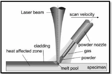
According to Vollertsen (2005) said that, the aim of laser cladding is the deposition of a cladding onto surfaces of work pieces in order to generate functional layers or regenerate the natural shape of parts. The material is deposited by powder injection, pre-placed powder or by wire feeding. In combination with the laser beam generating a melt pool the additional material is melted.
Figure 2.1: Principle of cladding process (Partes, 2005)
7
2.1.2 Heat Source for Cladding Process
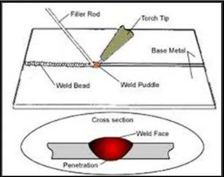
The successful of welding is about the source of heat which is performing of making the good weld pool. Basically, this fusion weld pool is place on the joint line. Figure 2.2 below shows that the schematic of weld pool on the workpiece.
Figure 2.2: The cross section of weld pool on the parent metal. (Vollertsen, 2003)
The weld pool area heated with heat source to be usable in welding conditions which is: a) The small heat source directly to the area of weld pool because of the size of
weld pool can be limited to change. When the heat source is large, it is not suitable to use in cladding process because it make the properties and the microstructure of parent metal change.
b) The heat source must operate at a higher temperature than the low heat transfer and the heat will spread over the area of weld pool.