TWO-DIMENSIONAL RUBBLE-MOUND
BREAKWATER MODEL USING TETRAPOD AT
ARMOR LAYER AND GEOTUBE AT CORE LAYER
Olga Pattipawaej
1, Hanny Dani
1, I. Putu Samskerta
2 1Universitas Kristen Maranatha, Faculty of Engineering,
Jl. Prof. drg. Suria Sumantri, MPH No. 65, Bandung 40164, Indonesia
2
Ministry of Public Works, Balai Pantai,
Jl. Gilimanuk Singaraja Km 122, Gerokgak, Buleleng Regency, Bali 81155 Indonesia
[email protected] (Olga Pattipawaej)
Abstract
Waves and currents can remove sand from the coastal areas that caused beach erosion. Beach
erosion needs to be handled by building breakwater. Rubble mound breakwater is chosen to
dissipate the wave energy. Rubble mound structures are widely used throughout the world; so
naturally, stability tests of rubble mound structures are the most frequently conducted coastal
structure model. Two-dimensional rubble mound structure physical model is carried out in a
flume. The armor layer facing the seaward uses tetrapods that are placed randomly and the
core layer is set to be stable by using geotube. Three different slopes of rubble mound model
facing the seaward is applied, i.e., 1:1.5, 1:2, and 1:2.5, respectively. There are also four
different water levels used, i.e., 38 cm, 54 cm, 63 cm, and 70 cm. The measured
parameters of this study are the wave height and wave period in front of and behind
the
breakwater
structure. The analysis that can be done
is
the wave absorber and transmission waves. The stability of the structure can be observed
in the form of displacement armor testing on the breakwater and at toe for a wide variety
of slope and water level variations.
Keywords: breakwater, geotube, physical model, rubble mound structure, tetrapod
Presenting Author’s biography
1.
Introduction
Beach erosion is the erosion of soil or rock that occurs when waves and currents remove soil or rock from the beach system. The loss of soil or rock causes the beach to become gradually eroded. Beach erosion also threatens coastal properties and infrastructure such as roads, homes, and businesses. If beach erosion is left untreated, there will be degradation, reducing the ability of the soil to bind the particles that cause the sliding of land on the seaside.
Breakwater is a structure on the coast to protect the coast against erosion. Type of breakwater structure used is usually determined by the availability of materials in or near the work site, the sea conditions, water depth, and the availability of equipment for the implementation of the work. Rubble mound breakwaters use structural voids to dissipate the wave energy. Rock or concrete armor units on the outside of the structure absorb most of the energy, while gravels or sands prevent the wave energy's continuing through the breakwater core.
The prediction of rubble mound breakwaters' stability is one of the most important issues in coastal and maritime engineering. Optimizing a rubble mound structure often can only be achieved by systematic physical model tests. In this paper, two-dimensional rubble mound structure physical model is carried out in a flume at Balai Pantai. Tetrapod is placed randomly at the armor layer of rubble mound structure model that facing the seaward. The core layer of rubble mound structure model is conditionally stable by using geotube. Three different slopes of rubble mound model facing the seaward is applied, i.e., 1:1.5, 1:2, and 1:2.5, respectively. There are also four different water levels used, i.e., 38 cm, 54 cm, 63 cm, and 70 cm. The measured parameters of this study are the wave height and wave period in front of and behind the breakwater structure. The analysis that can be done is the wave absorber and transmission waves. The stability of the structure can be observed in the form of displacement armor testing on the breakwater and at toe for the variety of slope and water level variations.
2.
Rubble Mound Structure
Coastal structures are intended to protect shoreline or navigation channels from the effects of waves and other hydrodynamic force. The design of coastal structures must consider a range of wave heights and periods combined with water level variations. The most common types of coastal structures are rubble mound structures, impermeable sloping structures, vertical wall structures, composite structures, floating structures, and pneumatic and hydraulic breakwaters [4].
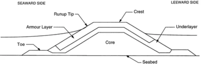
Rubble mound structure is used extensively for breakwaters, jetties, revetments, seawalls, and wave absorber. Rubble mound structures have a core of quarry-run stones, sand, slag, or other suitable materials protected from waves action by one or more stone under layers and a core layers of relatively large, selected quarry stones or specially-shaped concrete armor units [3]. Fig. 1 shows a typical cross section of a rubble mound breakwater. The core, shown in the cross section is usually composed of sand fill, and the armor layers are made up of more rock or the concrete armor units [2].
Fig. 1 Cross section of a typical rubble mound breakwater
allowing water to flow around rather than against it and to reduce displacement by allowing a random distribution of tetrapods to mutually interlock. The core layer is set stable by using geotube. Geotube is a sand material filled geotextile tube made of permeable but soil-tight geotextile (see Fig. 3).
Fig. 2 Tetrapod Model
Fig.3 Geotube Breakwater
3.
Experiment Set Up and Procedure
The experimental research was carried out in the wave flume of Laboratory Balai Pantai, Buleleng Bali. The wave flume is 40 m long, 0.6 m wide and 1.2 m high. It is equipped with a piston type wave generator that produces regular wave. Three wave probes are installed in the wave flume (Fig. 4).
Fig. 4 Side View of the Flume
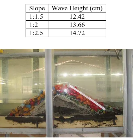
model with the slope 1:1.5. The rubble mound breakwater model is designed based on stability of rubble mound structure using Hudson formula [1]. The similarity of the rubble mound breakwater model is 1:10.
Tab. 1 Wave height at different slope of breakwater model
Slope Wave Height (cm)
1:1.5 12.42
1:2 13.66
1:2.5 14.72
Fig. 5 Side view of rubble mound breakwater model with slope 1:1.5
The water levels are conducted at four different water levels: 38 cm (mean low water level), 54 cm
(mean high water level), 63 cm (crest elevation), and 70 cm (submerged).
4.
Result and Discussion
Wave direction, either normally incident or oblique, refers to the direction of wave travel with respect to the breakwater axis [2]. The significant wave height is usually defined as the average of one-third highest wave (H13). Tab. 2 presents the significant wave height, runup, and rundown at 38 cm of
water elevation. It can be concluded that H13 and Ru−Rd at the mean low water level show the
smallest results at the slope 1:2.5 of the rubble mound breakwater model. It means that the highest energy of waves absorb at the slope 1:2.5 of the rubble mound breakwater model.
Tab. 2 Significant wave height, runup and rundown at 38 cm of water elevation
Format of Slope H13
When the water level is 54 cm or at the mean high water level, there is only rundown occurred. The rundown for each different slope of rubble mound breakwater model can be seen in Tab. 3. The wave absorber gives the highest value for the slope 1:2.5 of the rubble mound breakwater model.
Tab. 3 Rundown at the mean high water level
Format of Slope Rundown, R d (cm)
1:1,5 14.0
1:2 18.5
The elevation of the crest should be at minimum at which overtopping occurs. This should be based on maximum wave runup [2]. Tab 4 presents the overtopping at the water level at 63 cm with variation of slope of the rubble mound breakwater model that facing the seaward.
Tab. 4 Overtopping at 63 cm of the water elevation
Slope Overtopping (cm)
1:2 7.6
1:2.5 9.5
The wave transmission coefficient (K ) is defined as the ratio of the transmitted wave height (t H ) at t
the leeside to the incident wave height (H ) at the breakwater seaward, as follows i
i
The value of K indicates the effectiveness of a rubble mound breakwater at submerged condition to t
attenuate waves [5]. The value of K varies between 0 and 1. The value of zero implies that there is t no transmission. The value of 1 means no reduction in wave height (there is no barrier in front of the wave). The result of wave transmission coefficient is presented in Tab. 5 at the water level 70 cm (submerged).
Tab. 5 Wave transmission coefficient at the water level 70 cm
Slope
Based on the result of wave transmission coefficient, the slope 1:2.5 of the rubble mound breakwater model can reduced the wave height greater than the slope 1:1.5 and 1:2 of the breakwater model, respectively.
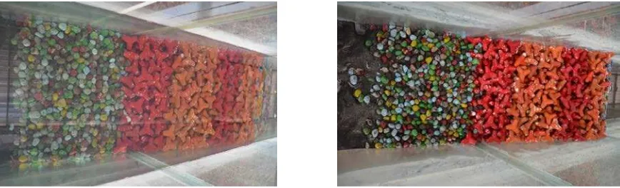
The stability of the structure can be observed in the form of displacement armor testing on the breakwater and at toe for the variety of slope and water level variations. Figs. 6, 7, and 8 show the documentation of displacement armor before and after testing for the slope 1:1.5, 1:2, and 1:2.5 of the rubble mound breakwater model, respectively. It can be seen from those figures that the armor units is not displace at the slope 1:2.5 of rubble mound breakwater model compare to the slope 1:1.5 and 1:2.
Fig. 7 Documentation of armor displacement before (left) and after (right) running for the slope 1:2 of the rubble mound breakwater model
Fig. 8 Documentation of armor displacement before (left) and after (right) running for the slope 1:2.5 of the rubble mound breakwater model
5.
Conclusions
The function of rubble mound breakwater is to protect the coastal area. Since the rubble mound breakwater need to be in stable condition, the two dimensional physical model of rubble mound breakwater is conducted by using three different slope, i.e., 1:1.5, 1:2, and 1:2.5 that facing the seaward side. The water levels are applied at the mean low water level, the mean high water level, the crest elevation and submerged using the flume with regular wave. The rubble mound breakwater model is designed based on stability of this breakwater using Hudson formula. The armor units of rubble mound breakwater model are tetrapod that is placed randomly facing the seaward. The core is set stable by using geotube. The wave absorber, transmission wave and displacement of armor units give the best result for the slope 1:2.5 of the rubble mound structure model. Further research is needed to conduct for three dimensional of rubble mound breakwater model generating by irregular waves.
Acknowledgments
The authors would like to thank DIPA Kopertis Wilayah IV, Ministry of Research, Technology, and Higher Education, the Republic of Indonesia, for providing the grant accordance with the Letter Agreement of Implementation Research Grant No. DIPA-023.04.1.673453/2015, on November 14, 2014 and the first revision on March 3, 2015. The authors would also like to thank Balai Pantai, Ministry of Public Works for providing the research facilities to undertake the research.
References
[1] CIRIA, CUR, CETMEF. The Rock Manual. The use of rock in hydraulic engineering, 2nd
edition, C683, CIRIA, London, 2007
[2] G. Palmer, and C.D. Christian. Design and construction of rubble mound breakwaters. IPENZ
[3] R.Y. Hudson. Laboratory Investigation of Rubble mound Breakwaters. Journal of the
Waterways and Harbors Division, American Society of Civil Engineers, Vol 85, No WW3, pp
93-121, 1959
[4] S.A. Hughes. Physical Models and Laboratory Techniques in Coastal Engineering. Advanced Series on Ocean Engineering, Volume 7. World Scientific Publishing Co. Pte. Ltd., River Edge, NJ, 1993.