UNIVERSITI TEKNIKAL MALAYSIA MELAKA
GRAPHENE AND CARBON NANOTUBE BASED
ELECTROCHEMICAL CAPACITOR IN AQUEOUS
ELECTROLYTE
This report submitted in accordance with requirement of the Universiti Teknikal Malaysia Melaka (UTeM) for the Bachelor Degree of Manufacturing Engineering
(Engineering Materials) (Hons.)
by
NURUL HAZIMAH BINTI JANTAN
B051110077
891105-04-5240
FACULTY OF MANUFACTURING ENGINEERING
DECLARATION
I hereby, declared this report entitled “Graphene and Carbon Nanotube Based Electrochemical Capacitor in Aqueous Electrolyte” is the result of my own research
except as cited in references.
Signature : ……….
Author‟s Name : NURUL HAZIMAH BTE JANTAN
APPROVAL
This report is submitted to the Faculty of Manufacturing Engineering of UTeM as a partial fulfillment of the requirements for the degree of Bachelor of Manufacturing Engineering (Engineering Materials) (Hons.). The members of the supervisory committee are as follow :
………
i
ABSTRAK
ii
ABSTRACT
iii
DEDICATION
I dedicated this entire work to my beloved family especially to my husband, my father and mother and also to my fellow friends, supervisor and lecturers for their
iv
ACKNOWLEDGEMENT
First and foremost, I would like to thank God for giving me the strength to carry out this course of research. Then, I would like to express my sincere thanks and appreciation to the following people and organization who have directly or indirectly given generous contributions towards the success of this academic study.
First in the list, I would like to express my sincere appreciation to my respectful supervisor, Dr. Mohd Asyadi „Azam b. Mohd Abid for his guidance, advice and encouragement throughout this project. I would like also to take this opportunity to thank my beloved parents and family members for their support, cares and kindness throughout the period study.
v
List Abbreviations, Symbols and Nomenclatures xi
CHAPTER 1 : INTRODUCTION 1
2.1.1 Electrochemical Double Layer Capacitor (EDLC) 8
2.1.2 Pseudocapacitor 9
2.2 Electrode Material 10
2.2.1 Carbon as Electrode Material 10
2.2.1.1 Graphene 11
2.2.1.2 Carbon Nanotube (CNT) 13
2.2.1.3 Other Carbon Materials 16
2.3 Electrolyte 17
2.3.1 Aqueous Electrolyte 18
2.3.2 Non Aqueous Electrolyte 19
2.4 Characterization Techniques 20
2.4.1 Electrode Characterization 21
vi
3.1 Electrochemical Capacitor Construction 28
3.2 Electrode Material Preparation 29
3.3 Fabrication Process to Produce the EC 35
3.4 Electrode Characteristic 35
3.5 Experimental Set up for CV Analysis 36
3.6 Set up for Prototype Development 37
CHAPTER 4 : RESULT AND DISCUSSION 40
4.1 Result of EC fabrication 40
4.2 Surface Morphology Analysis by SEM 42
4.2.1 EDX Analysis 44
4.3 Cyclic Voltammetry Analysis of The Fabricated EC 45
4.3.1 Specific Capacitance Value 45 4.3.4.2 Activated Carbon and SWCNT 56 4.3.4.2.1 6M KOH Electrolyte 57
4.3.5 Problem during CV Testing 59
4.4 Prototype Development 60
4.4.1 Fabrication of EC in the Coin Cell 60
vii
CHAPTER 5 : CONCLUSION AND RECOMMENDATION 64
5.1 Conclusion 64
5.2 Recommendation for Future Work 65
REFERENCES 66
APPENDIX A
Academic Achievement
APPENDIX B
viii
LIST OF TABLES
Table Title Page
1.1 Comparison of Batteries, ECs and Conventional Capacitors 2
2.1 Properties of Graphene 11
2.2 The Summary of Graphene 12
2.3 The Summary of CNT 14
2.4 Properties of Various Materials used in EC electrode materials 16 (Simon, 2008)
2.5 The Type of The Electrolytes and it Charge of the Ions 17 2.6 Comparison between Aqueous and Non Aqueous 19 2.7 Properties of Various Electrolyte (Simon, 2008) 20
3.1 Materials and its Function 29
3.2 Apparatus and Its Function 31
3.3 Materials used and its Weight 34
3.4 The Component to Produce Circuit 38
4.1 The Composition of Materials used in the Electrode Fabrication 40 4.2 The Composition of Materials used in the Electrode Fabrication 41 4.3 Mass of Different Electrode Materials 42 4.4 The Csp Result with Different Scan Rate 49
4.5 The Value of Csp for Different cycle 51
ix
LIST OF FIGURES
Figure Title Page
1.1 Plot of Power Density (Wkg-1) versus Energy Density (Whkg-1) of 2 Different Storage Devices (Rolison et al, 2009)
2.1 The Schematic EDLC (Retrieved from http://www.murata .com/) 8 2.2 The Operating Principle in Electrical Double-layer Capacitors 9
(Retrieved from http://www.murata .com/)
2.3 Schematic of Pseudocapacitor (Josie,2011) 9 2.4 A CV Potential Waveform with Switching Potentials 23
(Wang et al. 2000)
2.5 The Expected Response of Reversible Redox Couple during a Single 23 Potential Cycle (Wang et al. 2000)
2.6 A Schematic Cyclic Voltammogram of a Reversible Redox Process 25 (Si et al, 2008)
3.1 Flow Chart of Methodology 27
3.2 Example of EC Construction 28
3.3 Slurry Preparation 34
3.4 SEM Model EVO50 ZEISS 36
3.5 WonATech (WBCS3000) Voltammetry System 36
3.6 The Circuit for Testing EC 37
3.7 The Circuit for Testing EC 39
4.1 The Electrode with Carbon Material on Stainless Steel Mesh 41 4.2 Surface Morphology of Graphene and MWCNT as Electrode Material 43 4.3 Surface Morphology of Activated Carbon and SWCNT as Electrode 43
Material
4.4 EDX Analysis of Electrode Before use 44
x for 4 Hours
4.6 CV Curve with different Scan Rate 46
4.7 The Curve of EC in CV Analysis 48
4.8 The Shape of CV Curve with Different Scan Rate (Hsia et. al, 2014) 49
4.9 The Graph Csp versus Scan Rate 50
4.10 The CV Curve for 5 Cycles with Scan Rate 54 4.11 The CV Curve for 5 Cycles with Scan Rate 56 4.12 The CV Curve for 5 Cycles with Scan Rate 58
4.13 The Failed Shape in CV Curve 59
4.14 The Jig use in CV Testing 59
4.15 The Material and Equipment to Fabricate the EC 60 4.16 The Arrangement of EC in the Coin Cell Battery 61 4.17 The Crimping Process in the Glove Box 61 4.18 The Completed EC in the Coin Cell Battery 61
4.19 LED Circuit Model to Testing the EC 62
4.20 Common Adapter Charger 62
4.21 3V EC with 6M KOH Electrolyte 63
xi
LIST OF ABBREVIATIONS, SYMBOLS, AND
NOMENCLATURE
AC - Activated Carbon °C - Degree Celsius CNT - Carbon Nanotube Csp - Cpecific Cpacitance CV - Cyclic Voltammetry EC - Elecrochemical Capacitor
EDLC - Electrochemical Double Layer Capacitor EDX - Energy Dispersive X-ray
FGS - Functionalized Graphene Sheets H2SO4 - Sulfuric Acid
KOH - Potasium Hydroxide LiPF4 - Lithium
MWCNT - Multiwall Carbon Nanotube SEM - Scanning Electron Microscopy SSA - Specific Surface Area
1
CHAPTER 1
INTRODUCTION
1.1 Background
Nowadays, the need of energy has become increasing because both of households and industries require large amounts of power. Due to a lot of problems in environmental pollution, there is a need for green and clean renewable energy to assure the sustainable growth of communities As a result, the electrochemical capacitors (ECs) have become as an alternative to conventional electric energy storage device.
ECs, also known as supercapacitors or ultracapacitors are energy storage devices that combine the high energy storage capability of batteries with the high power delivery capability of capacitors (Burke, 2000). Basically, ECs can be classified into three types which are electrochemical double layer capacitors (EDLCs), pseudocapacitors, and hybrid capacitors. Among them, the EDLCs are the most common type for ECs because of the least cost to manufacture.
2
Figure 1.1 : Plot of power density (Wkg-1) versus energy density (Whkg-1) of different storage devices
(Rolison et al., 2009)
From Figure 1.1, the ECs resides in between batteries and conventional capacitors, these clearly shows that the ECs have both high energy density and power density than any other storage device.
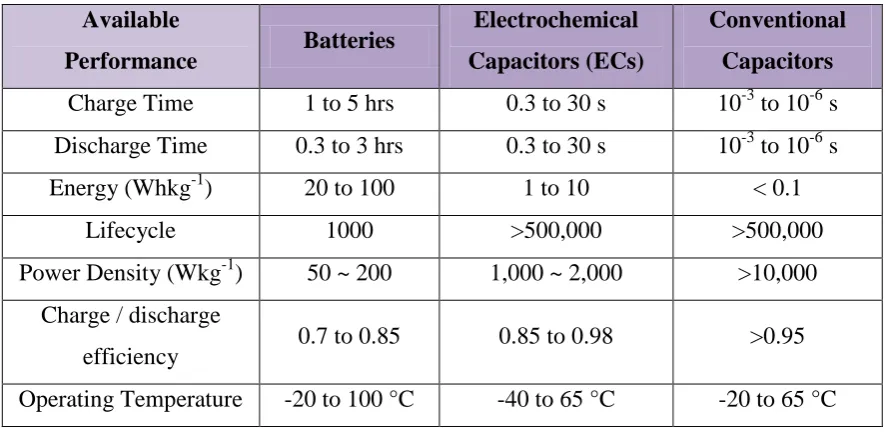
Table 1.1 : Comparison of Batteries, ECs and Capacitors (Rolison et al., 2009)
Available
Lifecycle 1000 >500,000 >500,000
Power Density (Wkg-1) 50 ~ 200 1,000 ~ 2,000 >10,000 Charge / discharge
3
Table 1.1 shows the comparison between the batteries, ECs can store large amount of amount of energy and power compared to conventional capacitors and battery compared to conventional capacitors. Furthermore, it also can be recharged in seconds rather than hours, it can withstand with cold temperature, shocks, and vibrations and it can be charged and discharged hundreds of thousands of times before they wear out. The EC is much easier on the environment than batteries, because the ECs contain earth abundant and nontoxic materials.
Although all the above devices have different mechanism, but there are also electrochemical similarities of these three systems. The common features are the energy providing processes that take place at the phase boundary of the electrode interface and the separation of electron and ion during the transportation processes.
4
1.2 Problem Statement
The production of energy by using the conventional method will leads to the global warming problems such as environmental pollution, petroleum exhaustion, climate change and the greenhouse effect. In response to reduce the output of carbon dioxide, the several countries have been decided to shut down the old nuclear power plants and not to build it with new ones. Apart from that, the energy demand has risen and the price of conventional energy sources has increased dramatically. This situation makes the reliance of national economies on a continuous and undistorted supply of such sources has become critical.
5
In order to increase energy storage, EC must use the porous materials as electrode in order to store ions in the pores at an atomic level. Usually the activated carbon is used to fabricate the EC‟s electrodes. The fact that activated carbon is not suitable as electrode material due to the charge carriers are larger size to the pores in the material and some of them cannot fit into smaller pores. As a result, it will reduce the storage capacity in the EC performance.
There are many factors that need to take as consideration in order to improve the energy density of the ECs such as type of electrode and electrolyte material. In this report, carbon material (graphene and carbon nanotube) will be used as electrode material because of its contributed to a high value capacitance. This is due to their special characteristic which is a porous material. The cyclic voltammetry (CV) will be used to measure the value of capacitance and to determine whether the fabricated EC is EDLC or pseudocapacitor, and lifecycle. If EC can increase its energy density in the future, then the use of the battery can be replaced.
1.3 Objectives
In this study, there are two parameters were made constant throughout the experiment which are the substrate (stainless steel mesh) and electrode material (graphene and CNT). The main objectives of this research are :
(i) To fabricate the EC by using graphene and CNT as the electrode material.
6
1.4 Scope of Research
7
CHAPTER 2
LITERATURE REVIEW
2.1 Electrochemical Capacitors (ECs)
8
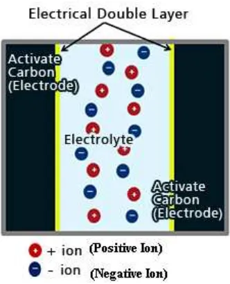
2.1.1 Electrochemical Double Layer Capacitor (EDLC)
Figure 2.1 : The Schematic EDLC (Retrieved from http://www.murata.com)
Figure 2.1 shows how an EDLC is made up from a separator, electrolyte, activated carbon and current collector. Usually the activated carbon is used as the electrode, because it gives the extremely high specific surface area, relatively low cost, ultra high capacitances are possible within a small package size. EDLC can achieve high life cycle seems it has no chemical reaction
9
Figure 2.2 : The Operating Principle in Electrical Double-layer Capacitors (Retrieved from
http://www.murata.com)
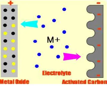
2.1.2 Pseudocapacitor
The pseudocapacitor is the combination of battery and capacitor. For EDLC the storage principle is electrostatically, whereas pseudocapacitors also store energy through a chemical reaction whereby a faradic charge transfer occurs between the electrolyte and the electrode. Pseudocapacitor is asymmetric in that sense that one of the two electrode layers is a carbon based capacitor electrode while the second electrode is similar with secondary batteries that use a transition metal oxide. The storage mechanisms are both reversible and can be charged and discharged 10000 of time. The Figure 2.3 shows how the pseudocapacitor is made up from faradaic reaction similar to the battery at the positive electrode. While in negative electrode, they use the double layer phenomena by using activated carbon with high surface area to give the great performance of pseudocapacitor. (Josie, 2011)
10 material that will use is graphene and CNT.
2.2.1 Carbon as Electrode Material
Carbon due to different allotropes (diamond, graphite, fullerenes/nanotube), various microtextures (more or less ordered) owning to the degree of graphitization, a rich variety of dimensionality from 0 to 3D and ability for existence under different forms (from powders to fibres, foams, fabrics and composite) represents a very attractive material for electrochemical application, especially for the storage of energy (Frackowiak et al., 2001).
EC can deliver and store energy at relatively high rates because the mechanism of energy storage is simple charge operation. The EC vasts increase in capacitance in achieved due to the combination of an extremely small distance that separates the opposite charges, as defined by the electric double layer; and highly porous electrodes that embody very high surface areas.
Carbon has becoming more atterctive as an electrode material due to its combination of chemical and physical properties such as high conductivity, good corrosion resistance, high surface–area (~1 to >2000 m2/g2), high temperature stability, controlled pore structure, and good processabillity and compatibility