PROPAGATION COVERAGE USING RAY-TRACING TECHNIQUE (FOR OUTDOOR SCENARIOS)
CHAI YONG PIN
UNIVERSITI TEKNIKAL MALAYSIA MELAKA
PROPAGATION COVERAGE USING RAY-TRACING TECHNIQUE (FOR OUTDOOR SCENARIOS)
CHAI YONG PIN
This report is submitted in partial fulfillment of the requirements for the award of Bachelor of Electronic Engineering (Telecommunication) with Honours
Faculty of Electronic and Computer Engineering
Universiti Teknikal Malaysia Melaka
ii
UNIVERSTI TEKNIKAL MALAYSIA MELAKA
FAKULTI KEJURUTERAAN ELEKTRONIK DAN KEJURUTERAAN KOMPUTER
BORANG PENGESAHAN STATUS LAPORAN
Saya CHAI YONG PIN, (HURUF BESAR) mengaku membenarkan Laporan Projek Sarjana Muda ini disimpan di Perpustakaan dengan syarat-syarat kegunaan seperti berikut:
1. Laporan adalah hakmilik Universiti Teknikal Malaysia Melaka.
2. Perpustakaan dibenarkan membuat salinan untuk tujuan pengajian sahaja.
3. Perpustakaan dibenarkan membuat salinan laporan ini sebagai bahan pertukaran antara institusi pengajian tinggi.
4. Sila tandakan ( √ ) :
SULIT*
*(Mengandungi maklumat yang berdarjah keselamatan atau kepentingan Malaysia seperti yang termaktub di dalam AKTA RAHSIA RASMI 1972)
TERHAD** **(Mengandungi maklumat terhad yang telah ditentukan oleh
organisasi/badan di mana penyelidikan dijalankan)
TIDAK TERHAD
Disahkan oleh:
__________________________ ___________________________________
(TANDATANGAN PENULIS) (COP DAN TANDATANGAN PENYELIA)
iii
“I hereby declare that this report is the result of my own work except for quotes as cited in the references”
Signature :………
iv
“I hereby declare that I have read this report and in my opinion this report is
sufficient in terms scope and quality the award of Bachelor of Electronic
Engineering (Telecommunication Engineering) With Honors”
Signature :………
v
DEDICATION
vi
ACKNOWLEDGEMENT
First and foremost, I would like to address my highest gratitude to my Final
Year Project Supervisor, Puan Juwita Binti Mohd Sultan for her sincere and
continuous assistance and guidance throughout the project. Without her, I would not
have complete my project and hence finish my Bachelor Degree in Electronic
Engineering (Electronic Telecommunication).
Also, not to forget about my fellow course mates and friends that have always
been around me to support and aid me whenever I need help. Their incessant support
had accompanied me throughout the hard time of the whole project. I would have
encountered mentally and physically depression by my own when tension and stress
of the project stroked me. I would like to greet them a sincere appreciation of mine
on this matter.
Last but not least, I would like to deliver a heartfelt thankfulness to my
beloved girlfriend who has always been around me when I need companion. I will be
vii
ABSTRACT
This report presents a study on the propagation coverage for general scenarios
using Ray-Tracing Technique. As transmitted signal propagates in the transmission
medium (outdoor scenarios), the signal power will come across reduction when it
reaches the receiver. The reduction is most probably caused by the obstacles that the
signal ray hit along the way of its transmission. Signal power reduction at the
receiver is dependent on three major factors, the separation distance between the
transmitter and the receiver, the materials present in the transmission medium and the
angle of incidence of the signal ray on the materials. The objective of this study is to
predict the coverage for general scenarios (outdoor scenarios) in terms of maximums
distance and obstacles in the vicinity. The output/coverage of the simulation have to
be done and shown in MATLAB 2D. The methodology is divided into four major
phases to systematically carry out the whole project; the Planning phase, the
Conducting phase, the Designing phase and the Analysis phase. At the closing stages,
the results shows that propagation coverage drops significantly when separation
distance of transmitter and receiver increases. Also, the results show that the power
received decrease as the angle of incidence of rays increase. This implies that power
received is reliant on the materials in the transmission medium to constitute the effect
viii
ABSTRAK
Laporan ini menunjukkan hasil kajian tentang propagasi liputan bagi scenario
umum dengan menggunakan Teknik Jejakan Sinar (Ray-Tracing Techique). Apabila
isyarat menyebar melalui medium penghantaran (senario luaran), pengurangan kuasa
isyarat akan berlaku apabila ia mencapai penerima. Pengurangan kuasa isyarat ini
berkemungkinan disebabkan oleh pemantulan sinar isyarat terhadap permukaan
bahan yang wujud dalam medium penghantaran. Pengurangan kuasa isyarat yang
diterima oleh penerima adalah bergantung kepada tiga faktor, iaitu jarak pemisahan
antara pamancar dan penerima, jenis bahan yang hadir dalam medium penghantaran
dan sudut kejadian isyarat pada bahan. Objektif kajian ini dijalankan adalah untuk
meramalkan liputan bagi senario umum (scenario luaran) bagi jarak maksimum dan
rintangan-rintangan di sekitarnya. Hasil kasian bagi liputan simulasi harus dilakukan
dan dipaparkan pada MATLAM 2D. Metodologi bagi kajian ini dibahagikan kepada
empat fasa secara sistematik untuk malaksanakan projek ini secara keseluruhan iaitu
fasa perancangan, fasa pembuatan, fasa rekaan dan fasa analisis. Pada tahap
penutupan, keputusan kajian menunjukkan bahawa liputan propagasi menurun
dengan ketara apabila jarak pemisahan antara pemancar dengan penerima meningkat.
Selain itu, keputusan juga menunjukkan bahawa kuasa yang diterima berkurangan
apabila sudut kejadian meningkat. Ini bermakna kuasa yang diterima adalah
bergantung kepada bahan di media penghantaran untuk membentukkan kesan Relatif
x
CHAPTER TITLE PAGE
II LITERATURE REVIEW 6
2.1. Wireless Mesh Network 6
2.2 Reflection, Refraction and Diffraction 11
2.3 Ray-Tracing Technique 12
2.4 Accuracy Of The Ray-Tracing Method 13
2.5 The Parameter in Propagation Prediction 14
2.6 Friis Transmission Equation 15
III PROJECT METHODOLOGY 21
3.1 Review of Project Methodology 21
xi
V CONCLUSION AND FUTUTE WORKS 49
xii
LIST OF TABLES
NO TITLE PAGE
3.1 Materials and their corresponding relative permittivity
and electrical conductivity
31
4.1 Power received of free space loss model for distance
1-100m
37
xiii
LIST OF FIGURES
NO TITLE PAGE
1.1 Brief flow chart of the project work piece 4
2.1 Wireless Mesh Network Topology 6
2.2 Three nodes mesh network 7
2.3 Four nodes mesh network 7
2.4 Five nodes mesh network 8
2.5 A comparison of a wireless peer-to-peer network, a
wireless LAN infrastructure network, and wireless mesh
networking.
10
2.6 The general situation of reflection and refraction in an
indoor environment.
11
3.1 Process flow chart 23
4.1 Power received versus distance R between transmitter
and receiver for free space loss model
39
4.2 Power received for multipath perpendicular reflection
effect versus separation of transmitter and receiver R
41
4.3 Power received for multipath parallel reflection effect
versus separation of transmitter and receiver R
43
4.4 Power received for multipath perpendicular transmission
effect versus separation of transmitter and receiver R
44
4.5 Power received for multipath parallel transmission effect
versus separation of transmitter and receiver R
45
4.6 Power received (perpendicular) versus separation of
transmitter and receiver R
xiv
4.7 Power received (parallel) versus separation of
transmitter and receiver R
1
CHAPTER 1
INTRODUCTION
This chapter shows the introduction of Wireless Mesh Network and
Ray-Tracing Technique, background of problem, objectives and scope of the study.
1.1 Introduction
Wireless Mesh Network (WMN) is an advance networking technology in this
coming future or perhaps, now. WMNs differ from conventional networking pattern
in terms of front-end facilities, width of coverage, transmission power, routing
capability, network maintenance etc. Regarding to all the existing advantages on
WMN, it is recently undergoing a rapid development and inspiring numerous
applications in potential fields/industries. Nevertheless, for a WMN to be all it can be,
considerable research efforts are still required. The WMN technology still possesses
several of setbacks that likely manipulate the performance and coverage of the
network. For example, the distances and obstacles that regularly led to signal power
reduction; the available MAC and routing protocols are not scalable; throughput
drops significantly as the number of nodes or hops in WMN raised etc. If the
majority of the mentioned hitches are solved or improved, WMN will be the next
2
This study is about employing the Ray-Tracing Techniques in resolving the
power received from the transmitted signal, through the aid of MATLAB
programming software.
1.2 Project Objectives
There are several objectives regarding to the project undergo that we need to
pay attention to so that we can gather all our efforts and time on these following aims
throughout the whole project. The following shows 3 majors objectives of the
projects:
1. To study and understand Ray Tracing Technique and Friis Transmission
Equation.
2. To predict the coverage in terms of the maximum distance and obstacles.
3. To study, understand and master the use of MATLAB 2D in order to visualize the output/coverage.
1.3 Problems Statements
1. Present the output coverage in MATLAB 2D.
2. The factors that will lead to reduction in signal strength.
3. The ways to improve these factors to obtain a better signal strength.
1.4 Project Scopes
1. The Ray Tracing technique and how it can be implemented to output the
coverage
2. Study and understand how to output the WMN coverage in MATLAB (2D) via
3
1.5 Project Methodology
In order to experience a better progression of the project, a brief flow or a
simple methodology is made to ease the monitoring of project so that it would stay
on the right path throughout the whole project.
For this project, it is distributed into four major phase of progress. It is shown
as below.
i. First Phase – Planning
Literature Review
Review on Objective and Scopes Identify key parameters
Work tools preparation
ii. Second Phase – Conducting
Data search and collection
Identify reliability of data and filter collected data Study and understand collected data
Arrange collected data
iii. Third Phase – Designing
Study and understand the work tools and software for the project
Identify relationship between collected data and the work tools for the project Design the coding for the simulation
Run the simulation
iv. Final Phase – Analyzing
Analyze the simulate results Discuss and explain on the results Conclude on the project
4
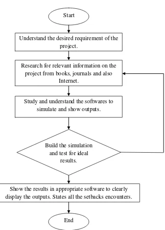
The following diagram shows the major steps that need to be taken before the
project can be completed.
Figure 1.1: Brief flow chart of the project work piece Show the results in appropriate software to clearly display the outputs. States all the setbacks encounters.
Start
Understand the desired requirement of the project.
Research for relevant information on the project from books, journals and also
Internet.
Study and understand the softwares to simulate and show outputs.
Build the simulation and test for ideal
results.
5
1.6 Report Structure
Chapter 1 of this report discuss generally epigrammatic introduction of the
whole project. It touches on the Introduction of this project and then proceed to the
Project Objectives. Also, this chapter includes the Problem Statements that might
encounter and the main Scopes of this project. Not to forget, this chapter comes with
the the project Methodology and the brief Report Structure of this writing.
Chapter 2 discuss mostly on the main concepts that governs this entire project.
It includes the Literature Review of the project where some of the important
principles are explained thoroughly.
Chapter 3will concentrate on the Methodology of this project. It discusses
about the methods and the processes taken to achieve the objectives of the project.
This chapter will explain the planning and methods taken phase by phase in details to
show a clear view on the process of the whole project.
Chapter 4 will discuss on the results obtained from the simulation via
working tools. As for this chapter, all the significant results will be shown to
demonstrate comparison of each and analysis will be performed to understand on the
behavior and characteristic of the outcomes.
Chapter 5 will give a summary on all the discussion on the results and draw a
logical conclusion on the obtained outcomes. Other than that, in this chapter the
future work of the project will also be discussed to explain the feasibility of the
6
CHAPTER 2
LITERATURE REVIEW
This chapter shows the basic principles of Wireless Mesh Network, the
concept of the Ray-Tracing Technique. Besides that, the implementation of Friis
Transmission equation in prediction of propagation coverage will also be discussed.
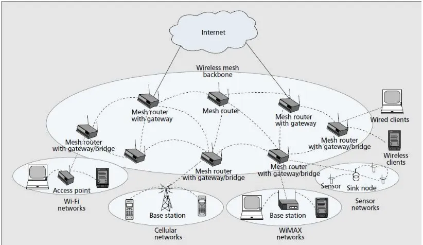
2.1 Wireless Mesh Network
7
Recently, wireless communication systems present increasing needs for
detailed planning that due to the reduction of cell size in mobile systems and the
rising number of wireless networks such in wireless Mesh Networks (WMNs). To
comprehend the mesh networking concept, we first need to obtain an appreciation for
what a mesh topology represents. If we have n nodes in a network, where the term
“node” refers to a communications device that can transport data from one of its
interfaces to another, then the ability of each node to communicate with every other
node in the network represents a mesh network topology.
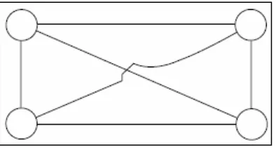
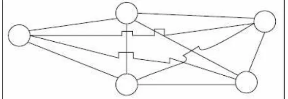
Figure 2.2 illustrates three, four, and five nodes mesh network structures, in
which each node has a communications connection to all other nodes in the network.
The connection between each node is referred to as a link. If we examine the number
of links associated with each network shown in Figure 1, it is obvious that the
number of links increases as the number of nodes increases. Although only three
links are required to interconnect three nodes, six are required to interconnect four
nodes, and ten are required to interconnect five nodes.
Figure 2.2: Three nodes mesh network
8
Figure 2.4: Five node mesh network
Basically, the ray-tracing techniques are used to model electromagnetic
environments by predicting the propagation paths between transmitters and receivers.
So, the effort is made when modeling each building and the environment as a whole
provides an important reduction of the complexity of the ray tracing process. But the
advantages obtained may be lost if ray tracing is not performed in the right way.
Instead of an indiscriminate ray tracing from the transmitter in all directions, a
selective ray tracing procedure may be used to obtain contributions at the receiver. A
ray will be traced only if it reaches a destination points or any nodes in a network.
Besides, if the rays intersect with an obstacle which generates a new reflected or
diffracted ray, it will also be traced. The computation time used in this process is
useful due to the contributions obtained. Then, the stop criterion in the ray tracing
procedure is the noise in the receiver. A certain level of noise in the receiver is
assumed. So, a ray will continue being traced until the value of the field associated to
it falls below the noise.
Wireless mesh networks (WMNs) are dynamically organized and
self-configured, with the nodes in the network automatically establishing an ad hoc
network and maintaining the mesh connectivity. WMNs are comprised of two types
of nodes: mesh routers and mesh clients. Router also called FFDs (Full Function
Devices), extend network area coverage, dynamically route around obstacles, and
provide backup routes in case of network congestion or device failure. They can
connect to the coordinator (device that sets up the network and acts as a portal to
monitor network performance and configure parameters) and other routers, and can
9
functions as a router and repeater, forwarding data to the next node to function as
relay.
Wireless Mesh Networks (WMN) is a decentralized networking technology
that is currently being adapted to connect peer to-peer clients and large-scale
backbone networks. Capacity of wireless networks is a very significant metric for
wireless mesh networks due to its highly distributed characteristics. To improve the
capacity for mesh networks, various high speed techniques for the physical layer are
being developed. Orthogonal Frequency Multiple Access (OFDM) in 802.11 is on of
the high-speed improvements in the Physical (PHY) layer for Wireless Local Area
Network (WLAN) used in mesh networks improving the speed from 11Mbps to
54Mbps at most. For Wireless Local Area Network (WLAN) there are two basic
types of WLAN networking structures, referred to as peer-to-peer and infrastructure.
In a peer-to-peer networking structure, each node can directly communicate with
every other node by assuming that they are in transmission range of each other. But,
in infrastructure WLAN networking environment, all traffic flow through an Access
Point (AP). But for WMN, in a nut shell it represents a series of peer-to-peer
transmission where each node functions as a router and repeater. On the other hand,
wireless LAN (WLAN) is a flexible data communication system implemented as an
extension to or as an alternative for, a wired LAN within a building or campus. Using
electromagnetic waves, WLANs transmit and receive data over the air, minimizing
the need for wired connections. Thus, WLANs combine data connectivity with user
mobility and through simplified configuration, enable movable LANs. Wireless
communication is without a doubt a very desirable service as emphasized by the
tremendous growth in both cellular and wireless local area networks (WLANs);
primarily, the ones that are compliant with the IEEE 802.11 family of standards,
popularly known as Wi-Fi (Wireless Fidelity). Ad-Hoc network is a wireless network
that is established without the aid of infrastructure or centralized administration.
Then, it is formed by a group of wireless terminals (nodes) such that communication
between any two terminals is carried out by means of a store and relay mechanism.
There also no fixed router in Ad-Hoc network. Nodes maybe mobile and can be
connected dynamically in an arbitrary manner. The node will be functioned as a