DEVELOPMENT OF THE AUDIT ENERGY SOFTWARE FOR OFFICE BUILDING BY USING VISUAL BASIC
NG SIEW WAN
This report is presented in
Partial fulfillment of the requirements for the
Degree of Bachelor of Mechanical Engineering (Thermal Fluid)
Faculty of Mechanical Engineering Universiti Teknikal Malaysia Melaka
ii
“I hereby, declare this thesis is result of my own research except as cited in the references”
Signature : ……….
Author’s Name : NG SIEW WAN
iii
iv
ACKNOWLEDGEMENTS
v
ABSTRACT
vi
ABSTRAK
vii
TABLE OF CONTENT
CHAPTER TOPIC PAGE
VERIFICATION ii
DEDICATION iii
ACKNOWLEDGEMENT iv
ABSTRACT v
ABSTRAK vi
TABLE OF CONTENTS vii
LIST OF FIGURES xi
LIST OF TABLES xiii
LIST OF ABBREVIATION xiv
LIST OF SYMBOLS xv
LIST OF APPENDIX xvi
CHAPTER 1.0 INTRODUCTION 1
1.1 Background Study 1
1.2 Problem Statement and Solution 2
1.3 Objectives 2
1.4 Scope 3
CHAPTER 2.0 LITERATURE REVIEW 4
2.1 Audit Energy 5
viii
CHAPTER TOPIC PAGE
2.1.1 Factors Affecting Energy Use in
Buildings 6
2.1.1.1 Size and Shape 7
2.1.1.2 Building Orientation 7 2.1.1.3 Planning & Layout 7
2.1.1.4 Window Systems 8
2.2 Software 8
2.3 Calculating Energy and Demand Balances 10
2.3.1 Lighting 10
2.3.2 Air Conditioning 11
2.3.3 Motors 11
2.3.4 Air Compressors 12
2.3.5 Other Process Equipment 12
2.4 Building Load 13
2.5 CLTD/SCL/CLF Method 13
2.6 Sample Development form of Audit Energy 15
2.7 Sample Audit Energy Report 16
2.7.1 Project Summary 16
2.7.2 Input Data 17
2.8 Sample Graph in Audit Energy Report 18
CHAPTER 3.0 METHODOLOGY 19
3.1 First stage: Surveying the Building through
Walk-Through 20
3.2 Second stage: Analysis of Energy Use and
Identification of Energy Projects 21 3.3 Third stage: Model Analysis Using
Computer Simulation 21
ix
CHAPTER TOPIC PAGE
3.5 Energy Audit Checklist 24
3.5.1 Lighting 24
3.5.2 Air-conditioning and Mechanical Ventilation Equipment and
Systems – HVAC 25
3.5.3 Wall Information 25
3.5.4 Window Information 25
3.5.5 Roofs and Floor 26
3.5.6 Internal Heat Gain Details 26
CHAPTER 4.0 RESULTS AND DISCUSSION 28
4.1 Model Calculation And
The User Interface 28
4.1.1 Cooling Load Method 28
4.1.2 External Cooling Load 29
4.1.3 Space Heat Gain and Space
Cooling Load- CLTD/CLF Method 29
4.1.4 Roof, Window and Wall 30
4.1.5 Internal Cooling Loads 30
4.1.6 Electric Lighting 30
4.1.7 People 31
4.1.8 Power Equipment and Appliances 32 4.1.9 Ventilation and Infiltration 33 4.2 Description about Simulation Program 34 4.3 The Guideline of Procedure for Using
Audit Energy Software 35
4.4 Manually Calculation - Sample
x
CHAPTER TOPIC PAGE
4.4.1 External Heat Gain 44
4.4.2 For Wall 45
4.4.3 For Roof 45
4.4.4 For Floor 46
4.5.5 For Window 46
4.4.6 Internal Heat Gain 46
4.4.7 People 47
4.4.8 Equipment and Appliances 47
4.4.9 For Lighting 48
4.4.10 Ventilation and Infiltration 49 4.5 The Result from the Audit Software 52
4.6 Future Work and Modification 55
CHAPTER 5.0 CONCLUSION 57
REFERENCE 59
BIBLIOGRAPHY 62
APPENDIX 63
xi
LIST OF FIGURES
NO TITLE PAGES
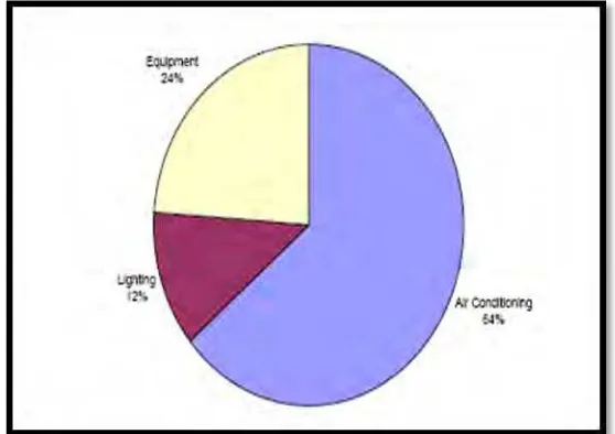
2.1 Novozymes Office Building Energy Load 6
2.2 Sample development form for Audit Energy project. 15
2.3 Sample project summary for Audit Energy Report 16
2.4 Sample Input Data for Audit Energy Report 17
2.5 The sample graph of “Annual Energy Consumption of sample Building in 2002 to 2006” for Audit Energy report 18
2.6 The sample graph “Monthly Energy Utilization Index & Building Energy Performance” for Audit Energy report 18
3.1 Steps to set up Data access 23
3.2 The flow chart showing the methodology of design
audit energy 27
4.1 The Login Audit Energy for office building 36
xii
NO TITLE PAGES
4.3 The General Project Data Audit Energy for office building 38
4.4 The Lighting System Audit Energy for office building 39
4.5 The Building Characteristic Audit Energy for office building 40
4.6 The Infiltration and Ventilation Interface Audit Energy
for office building 41
4.7 The Others (Miscellaneous) Audit Energy for office building 42
4.8 The Total Cooling Load Audit Energy for office building 43
4.9 The total heat gain from the Building Characteristic
Audit interface 52
4.10 The total heat gain from the Lighting system Audit interface 52
4.11 The total heat gain from the Infiltration and
ventilation Audit interface 53
4.12 The total heat gain from the Miscellaneous Audit interface 53
4.13 The total heat gain from the General Project Data
Audit interface 54
4.14 The total cooling load for first floor and total
xiii
LIST OF TABLES
NO TITLE PAGES
4.1 Rate of heat gains from occupants in conditioned spaces 32
4.2 The relationship between the type of usage, ventilation heat
gains, room moisturized and heat gain from people 34
4.3 Infiltration air constant 34
4.4 The construction material specification for an office building 44
4.5 Total heat gain for various types of equipment and appliances 48
4.6 Ventilation / infiltration load. 50
xiv
LIST OF ABBREVIATION
MIEEIP Malaysian Industrial Energy Efficiency Improvement Project DOE 2 Designs of Experiments 2
BLAST Building Loads Analysis and System Thermodynamics
RFM Response Factor Method
WFM Weighting Factor Method
CLTD Cooling load temperature difference SCL Solar cooling load factor
CLF Cooling load factor
TFM Transfer Function Method
ASHRAE American Society of Heating, Refrigerating and Air Conditioning Engineers
CTF Conduction transfer factors
WF Weighting factors
ECOs Energy-conserving opportunities AHUs Air handling units
VAV Variable air volume device CAV Constant air volume device ADO.Net ActiveX Data Objects
XML Extensible Markup Language ODBC Open Database Connectivity
xv
LIST OF SYMBOLS
Qrs = Sensible cooling load from roof (W)
A = Area (m2)
U = Overall heat transfer coefficient(W/m2. ºC) Qles = Sensible heat released from electric lights (W) Fuse = Use factor defined as the ratio of wattage Fal = Special allowance factor for fluorescent fixtures Qps = Space sensible for people (W)
Qpl = Latent cooling loads for people (W)
n = Number of people in the conditioned space SHG = Sensible heat gain per person (W)
LHG = Latent heat gain per person (W)
Qs = Sensible loads from power equipment and appliances (W) Ql = Latent loads from power equipment and appliances (W)
Qs,v = Sensible heat transfer due to the ventilation and infiltration (W) Ql,v = Latent heat transfer due to the ventilation and infiltration (W) N = Number of people in/out per hour (m3)
kc = Infiltration air constant ( m3/hr/ person) (To – Ti) = Temperature difference (ºC)
(Wo– Wi) = Indoor and outdoor humidity ratio CFM = Air flow rate
xvi
LIST OF APPENDICES
NO TITLE PAGES
A GANTT CHART 62
B PROGRAMMING CODES 64
1
CHAPTER 1
INTRODUCTION
1.1 Background Study
2
The role of an environmental auditor is to show participating offices the link between actions taken in the office and their effect on the environment. All these mean savings in money. Thus in this paper, it would like to propose audit energy software for office building by using Visual Basic Software in order to minimize the cost of energy usages. Betweens the design software will be work in rapid, accurate and cost-effective energy-auditing.
1.2 Problem Statement
Building cooling load components are; direct solar radiation, transmission load, ventilation and infiltration load and internal load. Calculating all these loads individually and adding them up gives the estimate of total cooling load. The load, thus calculated, constitutes total sensible load. Manual calculation step by step procedure has been carried out. There are a lot of times and energy is wasted when estimating the cooling loads in complex and intricate buildings of modern time. Besides that, the building characteristic have been describe such as type of material roof and wall for a building, daily indoor or outdoor temperature, area of each room, location latitude of building, operating hours, types of electrical component used and others in the building. So in this research develop the audit energy software for office building by using Visual Basic, to handle simple, intricate and dynamic nature of load estimate in Malaysia.
1.3 Objectives
a) To understand the principles, standard of theories through a literature study.
3
c) To complete develop of audit energy software for office building. d) To understand the function of visual basic.
1.4 Scope
4
CHAPTER 2
LITERATURE REVIEW
5
2.1 Audit Energy
Energy audits are a systematic study or survey to identify how energy is being used in a building or a plant. It is also a useful procedure to find out the best options for energy conservation. Energy audits provide an analysis of the amount of energy consumed during a given period in the form of electricity, gas, fuel, oil or steam. Using that information, it is possible to list how the energy was used according to the various processes in a plant or at the various outlets in a building (Ibrahim, 2001).
The Malaysian Industrial Energy Efficiency Improvement Project (MIEEIP) has successfully conducted energy audits for 48 factories from eight energy intensive sectors in Malaysia making it the largest ever national-based energy audit program. An analysis of the audit findings from 43 out of the 48 energy audits conducted by the MIEEIP were available showed that these 43 factories consumed approximately 31.78 million GJ of energy a year, or about 13.1 percent of the final energy commercial demanded by the eight targeted industries. The recommendation put forth by the audit team range from the improvement in housekeeping for existing equipment, retrofitting or replacing key equipment or process, to the installing of cogeneration plants. According to the energy audits, if all measures recommended are implemented by each factory, electricity usage will be reduced by 5.6 percent and fuel demand by 26.7 percent annually that will result total energy savings of 22.3 percent per annum for all 43 factories.
6
[image:22.612.205.484.135.332.2]kWh/m2/year. The 2003 audit confirmed the accuracy of the Energy-10 computer simulation.
Figure 2.1: Novozymes Office Building Energy Load (Source: Chan, (2004))
2.1.1 Factors Affecting Energy Use in Buildings
The building related factors influencing energy requirements are numerous and complex. They can be classified under the following heading (Chan, 2004).
1. Size and Shape 2. Orientation
3. Planning and Organization
4. Thermo physical properties – thermal resistance & thermal capacity 5. Window systems
7
2.1.1.1Size and Shape
Generally, a larger building will require more energy to cool than a smaller building because of the larger of space to be cooled. The larger buildings need less energy per unit size because of their smaller surface area per unit size and thus lower heat gain per unit size. Based on this theory they said “The larger a building, and the nearer to spherical in shape, the less are its energy needs because of the simple reduction in the ration of surface area to volume”. They conclude that “The architectural fad for angular protrusions of buildings is an energy wasting form”.
2.1.1.2 Building Orientation
Building orientation affects the air conditioning / heating energy requirements in two respects by its regulation of then influence of two distinct climatic factors.
• Solar radiation and its heating effects on walls and rooms facing different directions.
• Ventilation effects associated with the relation between the direction of the prevailing winds and the orientation of the building.
Solar influence on energy is the most significant in the tropics and is extensively covered by many others.
2.1.1.3Planning & Layout
8
1. Grouping of spaces 2. Interaction of spaces
3. Ceiling height and space volume
2.1.1.4Window Systems
The size, location, shape and orientation of glazed areas in a building will have a critical effect on both the heat gains and solar gains of a building because glazed areas have the highest hat gain per unit area and the major proportion of solar gains are also through windows.