i
DETERMINATION OF AERODYNAMIC DRAG FORCE ACTING ON MOVING HEAVY DUTY TRUCK-TRAILER IN MALAYSIA
MOHAMAD HAFIZ BIN MOHAMAD
This report is presented in
Partial fulfillment of the requirements for the
Degree of Bachelor of Mechanical Engineering (Automotive)
Faculty of Mechanical Engineering Universiti Teknikal Malaysia Melaka
ii
“I declare this report is on my own work except for summary and quotes that I have mentioned its sources”
Signature :
Name of Author : MOHAMAD HAFIZ BIMOHAMAD
iii
iv
ACKNOWLEDGEMENT
I am sincerely appreciative to Mr Mohd Hanif for giving me chances and opportunity to get involved in this project. A lot of thank for him for being cooperate and for serving as my supervisor and for providing guidance while conducting the research and the writing of this Projek Sarjana Muda (PSM).
First of all, thank to my beloved parent who always being support me since the beginning of this project. Also thank to my entire friend especially to my classmate for their cooperation during the project period and in term to successful complete this report.
I thank to the Mechanical Faculty management especially to the lecturer who get involve directly or indirect and for their commitment to help student to completely done the PSM. A lot of thanks also to the laboratory for their cooperation and commitment during the lab session.
v
ABSTRACT
vi
ABSTRAK
vii
CONTENTS
CHAPTER SUBJECT PAGE
DECLARATION ii
DEDICATION iii
ACKNOWLEDGEMENT iv
ABSRACT v
ABSTRAK vi
CONTENTS vii
LIST OF FIGURES x
LIST OF TABLES xii
LIST OF SYMBOLS xiii
CHAPTER I INTRODUCTION 1
viii
CHAPTER II LITERATURE REVIEW 7
2.1 2.2 2.3 2.4 2.5 2.6 2.7
The Aerodynamic of Heavy Vehicle
Historical Development on Heavy Vehicle Aerodynamic
Aerodynamic Concept 2.3.1. Drag
2.3.1.1. Coefficient of drag, Cd 2.3.2.Lift
Drag Relationship 2.4.1. Streamlines 2.4.2. Motion of Air
2.4.3. Laminar and turbulent Boundary layer 2.4.4. Flow Separation
2.4.5. Density and Viscosity of Air 2.4.6. Reynolds Number
2.4.7. Pressure Coefficient Wind Tunnel
Computational Fluid Dynamics ( CFD) Conclusion 7 8 12 13 15 18 19 19 20 20 21 22 22 23 24 25 26
CHAPTER III METHODOLOGY 27
3.1 3.2 3.3 3.4 3.5 3.6 Introduction Flow Chart Review 3.2.1. Theoretical Preview Reference Model
3.3.1.Truck Model For Computational Fluid Dynamic (CFD) Simulation
Numerical Model Setup Meshing
Solver Control
3.5.1. Choosing the Solver 3.5.2. Material Parameter
ix
3.7
3.5.3. Boundary condition parameter 3.5.4. Numerical Schemes and strategies Conclusion
37 38 38
CHAPTER IV RESULT AND DISCUSSION 39
4.1 4.2 4.3 4.4 4.5 Introduction
Flow Visualization Present Pressure Distribution Drag Coefficient Value
Discussion and the Recommendation for Improvement
4.5.1. Suggestion Model
4.5.2. Improvement Truck-Trailer Model Result 39 40 42 44 45 46 47
CHAPTER V CONCLUSION AND RECOMMENDATION 50
x
LIST OF FIGURES
NO SUBJECT PAGE
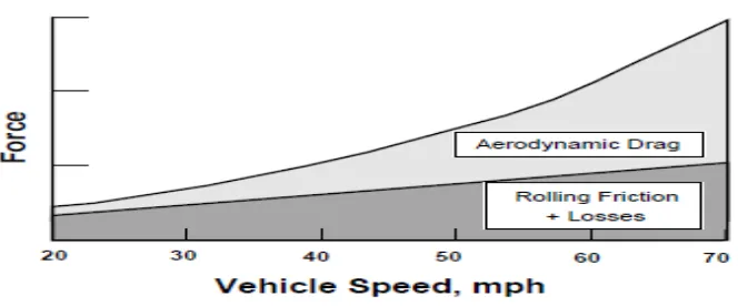
2.1 Graphic depicting representative horsepower requirements versus vehicle speed for a heavy vehicle tractor-trailer truck
8
2.2 1947, Labatt Streamliner 9
2.3 Show smoke flow over the standard tractor-trailer (a) and modified Tractor-trailer added with deflector
(air shield),(b)
10
2.4 Show Smoke Flow over the Standard Straight Truck (a), and
modified straight truck added with nose cone (b).
11
2.5 Aerodynamic resistance on vehicle body 12
2.6 The Effect of drag in Term of Speed Factor. 14
2.7 Aerodynamic resistance coefficient for passenger car 15
2.8 Distribution of aerodynamic resistance between (a) tractor and semi trailer and (b) truck and trailer at different yaw
angles.
17
2.9 Effect of add-on device and body detail on aerodynamic
resistance coefficient of tractor-trailers
17
2.10 The acting of lift force towards truck 18
2.11 Smoke-flow visualization over truck 19
2.12 Variation of Boundary Layer along a Flat Plate 20
2.13 A bluff vehicle shape-the flow separate from the top of cab and from the front edge or trailer
21
2.14 The acceleration of air when flow from high pressure to a low one, and slow down when flowing from a low pressure to
a high one
23
3.1 Flow chart of the research study 28
xi
3.3 Mercedes Benz 1838LS Tractor –Tank Trailer model 31
3.4 3D modeling Using CATIA VR 16 32
3.5 Simplify 3D surface modeling using CATIA V5R 16 33
3.6 CAD model ( IGES format ) in the GAMBIT. 33
3.7 2D meshing 34
3.8 3D meshing 34
3.9 Numerical model for CFD simulation 35
3.10 Boundary condition for the model 37
4.1 A bluff vehicle shape 40
4.2 Boundary layer growth 41
4.3 Vortices formation on the wake area 42
4.4 Pressure distribution on front view 43
4.5 Pressure distribution on the side view 43
4.6 Pressure distribution on the bottom view 44
4.7 Standard Cab-roof Fairing Measurement 45
4.8 New cab-roof fairing design 46
4.9 Improvement Cab-roof Fairing Measurement 46
4.10 Streamline flow for a new cab-roof fairing design 47
4.11 Show simulation flow for a standard cab-roof fairing design (a) and simulation flow for a new cab-roof fairing design (b)
xii
LIST OF TABLES
NO SUBJECT PAGE
2.1 Value of Aerodynamic Resistance Coefficient for Various Type of Vehicle
16
3.1 Mercedes Benz 1838LS Tractor –Tank Trailer
model Specification
31
3.2 Boundary Condition Parameter 38
4.1 Drag Coefficient value for standard truck-trailer model
44
xiii
LIST OF SYMBOLS
A = Frontal area m2 CD = Drag coefficient
Dp = Pressure drag Df. = Friction drag
ρ = Density, kg/m3 v = Speed, m/s
Re = Reynolds number
ɭ = Turbulence length scale
1
CHAPTER I
Introduction
1.1. Background
In commercials vehicle study such as heavy vehicle, the external flow remains the famous criteria to be concern. When the truck is in dynamic condition, the air exerts a force through it frontal area and this situation will resists a motion between them. This force is known as aerodynamic drag, and it has a significant impact on the performance of steady horizontal travel at normal road speeds.
The pressure drag will produce due to its body shape, frontal area and its speed on the road. The drag coefficient directly relates with the vehicle shape to the amount of air resistance experienced. By doing some modifications on its shape to be more streamlined flow, the value of drag coefficient, Cd can be reduce hence its result is better than before.
1.2.Objective
The objectives of this project are:
1. To determine the drag coefficient of typical heavy duty truck moving on the highways.
2. To simulate the flow conditions in CFD software and attempt to correlate the findings.
2
1.3. Scope
1. Determination of drag coefficients for heavy duty truck-trailer vehicle in terms of a numerical value CD.
2. Determination of Numerical values of pressure drag and skin friction drag for the truck bodies.
3. Study the effect of front pressure drag and cab-trailer drag on the aerodynamic performance of vehicle.
1.4. Problem Statement
In real life, the significant of aerodynamic term is referring to the vehicle design and its styling concept. The good styling design in vehicle is ability on the aerodynamic function which is more streamline flow and produce low pressure drag. A poor initial aerodynamic design is increases the overall drag on a vehicle hence creates the turbulence flow around the vehicle body.
In heavy vehicle reduction method, the substantial improvements can be readily achieved by using add-on aerodynamic styling features. This is because a lot of money is required to replace with the new truck if compare to the add on features.
3
1.5. Project Outline
The outline of this project is planning to ensure the flow of this research study is done properly. Besides that, this outline also can help the readers to fully understand the objective and the content of the study.
Begin from the Chapter 1 the summary of the project is presented. It consist the objective and scope of project, background project and the problem statement for this study.
In chapter 2, the stage is presented the documentation of literature review this chapter is consist of aerodynamic of heavy vehicle, previous development on truck aerodynamic, aerodynamic concept and its factor, Computational Fluid Dynamics (CFD). This chapter will be the knowledge source and the understanding about the aerodynamic theory.
The Methodology session in Chapter 3 is about the project flow from the starting until the end. In this chapter a briefly explain the creation the numerical model. It consists of the theoretical for the CFD simulation solution solver and the parameters as a model setup.
Chapter 4 is the discussion stage where the result and the finding are presented. It consists of the explanation for the data and the problem occurred since the research begins and the update design to improve the finding result.
5
1.6. Outline Gant Chart
Planning For PSM1
No Item Weeks
July-October
1 2 3 4 5 6 7 8 9 10 11 12 13 14
1 Introduction 2
2 Study on The Previous Aerodynamic Development 2
3 Study The Related Aerodynamic Theory 3
4
Study The Truck Model Shape and Measure The
Dimension 2
5 Develop 3D Truck Modeling Using CATIA VR16 4 6 Understanding The Relation Cd With Testing Method 2
5
Planning For PSM2
NO ITEM WEEK(S)
January - April
1 2 3 4 5 6 7 8 9 10 11 12 13 14
1 Study / Make Improvement to PSM1 3
2 Study and Explore GAMBIT and CFD Software 8
3 Simplified ( rebuild) trailer CAD model 2
4 Meshing and CFD Simulation 5
5 Analyze The Data and Make Discussion 2
6
Reshape / Improve Truck Cab-Roof Fairing Design and
Recommendation 2
6
1.7. Conclusion
7
CHAPTER II
LITERATURE REVIEW
2.1. The Aerodynamic of Heavy Vehicle
The performance of tractor-trailer trucks shows, the primary resistance forces are drive train losses, rolling friction, and aerodynamic drag. This situation make vehicle speed increase the force required to overcome both aerodynamic drag and rolling friction increases.
However, the rate of increase in aerodynamic drag due to increasing vehicle speed is much greater than rolling friction. As shown in (Figure 2.1), the force required to overcome aerodynamic drag was exceeds compare to the requirement to overcome rolling friction.“The higher the speed the more energy consumed in overcoming aerodynamic drag” (Rose McCallen, etl. al.(2000).
8
Figure 2.1. Graphic depicting representative horsepower requirements versus vehicle speed for a heavy vehicle tractor-trailer truck.( Rose McCallen ,etl. al., 2000)
The aerodynamic design of heavy trucks is presently based upon estimations of performance derived from wind tunnel testing.( Rose McCallen, etl. al., 2000). Besides that the estimation and prediction of aerodynamic performance can be done using the CFD. By doing this estimation, the trucking manufacturer or community has focused on reducing the aerodynamic drag of the forward facing surfaces of both the tractor and trailer. Normally aerodynamic drag will be reduce through aerodynamic shaping of the tractor cab and the forward face of the trailer by adding aerodynamic fairings to the trailer in order to direct the flow away from the trailer front face.
2.2. Historical Development on Heavy Vehicle Aerodynamic
9
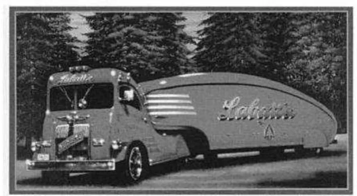
[image:22.595.114.469.217.412.2]The great achievement of this project is shown by the comparison when the Labatt truck can travel at 50 mil/h with a fifty percent large load while the truck of the day travelled at 35 mi/h. But nowadays the truck manufacturing is focus more on the energy conservation in term to minimize the usage of fuel because the fuel price is increase over the years
Figure 2.2: 1947, Labatt Streamliner (Rose McCallen , etl ,2004)
According to the Rose McCallen, etl , 2004 in their book The Aerodynamics of Heavy Vehicles: Trucks, Buses and Trains, the effort to improve truck performance and fuel consumption has been done since 1950’s. This project, funded by Trailmobile which was undertaken by the University Maryland to investigate the aerodynamic of tractor and trailers.
On 1960’s Seldon Saunders and Chet Willey done the detail look at truck aerodynamic include edge rounding, rounded trailer front face, skirts and boat-tailing. They provoked a new development of the air deflector called Airshield which is the add-on aerodynamic device. The next develop, Nose Cone trailer streamlining fairing which was realized by Fritzgerald when he working at Thermoking.
10
The National Research Council of Canada (NRC) took the task of comparing the commercial device of the day on the late 1970s.
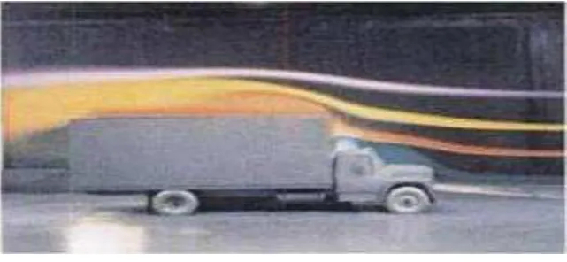
(a)
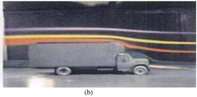
[image:23.595.150.471.610.758.2](b)
Figure 2.3: Show smoke flow over the standard tractor-trailer (a) and modified Tractor-trailer added with deflector (air shield),(b). (RoseMcCallen, etl, 2004).
11
[image:24.595.155.478.72.232.2](b)
Figure 2.4: Show Smoke Flow over the Standard Straight Truck (a), and modified straight truck added with nose cone (b). (Rose McAllen, etl, 2004)
During the late 1970s and early 1980s the SAE and US DOT, leading to the SAE/DOT Voluntary Bus and Truck Fuel Economy study on the aerodynamic reduction activities. This government/industry cooperative venture was to demonstrate the reduction of truck fuel consumption. It concentrates on a set of four pairs of truck, two tractor trailer combinations and straight truck. Each pair of truck consisted of a standard truck for the time and identical partners fitted with an aerodynamic package and were tested on the road and run in fleet service.