DESIGN OF LINEAR CONVEYOR FOR PARTS
FEEDING TO COMAU ARTICULATED ROBOT
AHMAD FADHLI BIN AHMAD RABUAN
B051010147
UNIVERSITI TEKNIKAL MALAYSIA MELAKA
DESIGN OF LINEAR CONVEYOR FOR PARTS FEEDING TO
COMAU ARTICULATED ROBOT
This report submitted in accordance with requirement of the Universiti Teknikal Malaysia Melaka (UTeM) for the Bachelor Degree of Manufacturing Engineering
(Robotics and Automation) (Hons.)
by
AHMAD FADHLI BIN AHMAD RABUAN B051010147
860505265689
SUPERVISOR: PROF. DR. BASHIR MOHAMAD BIN BALI MOHAMAD
UNIVERSITI TEKNIKAL MALAYSIA MELAKA
BORANG PENGESAHAN STATUS LAPORAN PROJEK SARJANA MUDA
TAJUK: Design of Linear Conveyor for Parts Feeding to COMAU Articulated Robot
SESI PENGAJIAN: 2013/14 Semester 2 Saya AHMAD FADHLI AHMAD RABUAN
mengaku membenarkan Laporan PSM ini disimpan di Perpustakaan Universiti Teknikal Malaysia Melaka (UTeM) dengan syarat-syarat kegunaan seperti berikut: 1. Laporan PSM adalah hak milik Universiti Teknikal Malaysia Melaka dan penulis. 2. Perpustakaan Universiti Teknikal Malaysia Melaka dibenarkan membuat salinan
untuk tujuan pengajian sahaja dengan izin penulis.
3. Perpustakaan dibenarkan membuat salinan laporan PSM ini sebagai bahan pertukaran antara institusi pengajian tinggi. atau kepentingan Malaysia sebagaimana yang termaktub dalam AKTA RAHSIA RASMI 1972)
(Mengandungi maklumat TERHAD yang telah ditentukan oleh organisasi/badan di mana penyelidikan dijalankan)
DECLARATION
I hereby, declared this report entitled “Design of Linear Conveyor for Parts Feeding to COMAU Articulated Robot” is the results of my own research except as
cited in references.
Signature : ……….
Author’s Name : ………
APPROVAL
This report is submitted to the Faculty of Manufacturing Engineering of UTeM as a partial fulfillment of the requirements for the degree of Bachelor of Manufacturing Engineering (Robotics and Automation) (Hons.). The member of the supervisory is as follow:
i
ABSTRAK
Penghantar adalah alat mekanikal yang biasa digunakan untuk menggerakkan barangan di dalam kilang. Penghantar dalam industri pembuatan digunakan secara meluas di pelbagai jenis sektor pembuatan seperti pembungkusan, pemindahan barangan, pick dan place (memilih dan meletak), dan lain-lain. Objektif projek ini adalah untuk mereka bentuk penghantar linear bagi hantaran bahan kerja kepada Robot COMAU Articulated. Idea mereka bentuk penghantar adalah berdasarkan sebahagian atau bahan kerja yang akan memilih dan meletakkan oleh lengan robot. Perisian untuk mereka bentuk penghantar juga telah dipilih berdasarkan pengetahuan penulis. Reka bentuk beberapa idea telah dihasilkan dan dibahagikan kepada dua komponen iaitu bingkai belt dan kaki penyokong. Dari lakaran idea ini, perbandingan telah dibuat untuk memilih idea rekabentuk yang lebih baik. Idea yang dipilih telah direka dengan perisian SolidWorks di mana setiap bahagian penting penghantar direka berdasarkan spesifikasi dan kehendak untuk hantaran bahan kerja kepada Robot COMAU Articulated. Penyenaraian semua parts yang perlu di proses dan
parts yang standard dibentangkan dalam laporan ini. Reka bentuk pemasangan dan
ii
ABSTRACT
iii
DEDICATION
iv
ACKNOWLEDGEMENT
v
List of Abbreviations, Symbols and Nomenclatures x
vi
2.8.2 Photoelectric sensors 12
2.9 Integration of Conveyor with Robot 13
2.10 COMAU Articulated Robot 14
2.11 Pick and place robotic system 16
2.12 Computer-Aided Design (CAD) software 17
2.12.1 AutoCAD 17
3.2 Generate preliminary design ideas and specification 23 3.3 Analysis of the preliminary design ideas and specification 26
3.4 Conclusion 27
CHAPTER 4: DESIGN AND ANALYSIS OF THE CONVEYOR 28
4.1 Conveyor design 28
4.1.1 Conveyors parts 28
4.1.2 Bill of materials 30
4.1.3 Assembly design and conveyor structure tree 32
4.1.4 Parts specification 34
4.1.5 Conclusion 40
4.2 Analysis 41
4.2.1 Simulation of Aluminium profile supporter legs 41
4.2.1.1 Model information 42
4.2.1.2 Material properties, loads and fixture 43
4.2.1.3 Mesh information 44
4.2.1.4 Result from analysis 46
4.2.2 Simulation of drive pulley 50
vii 4.2.2.2 Material properties, loads and fixture 51
4.2.2.3 Mesh information 52
4.2.2.4 Result from analysis 54
4.2.3 Motor power consumption calculation 57
4.2.4 Cost estimation 58
4.2.5 Conclusion 59
CHAPTER 5: CONCLUSION AND SUGGESTION FOR FUTURE WORK 60
5.1 Conclusion 60 G Detail of parts dimension
viii
LIST OF TABLES
3.1 The comparison for design ideas of belt frame 26 3.2 The comparison for design ideas of supporter legs 26 4.1 List of parts need to be fabricated and the standard parts as in Figure 4.1 30
4.2 Bill of materials for conveyor belt 31
4.3 Parts design and specification 34
4.4 Parameter for the solid bodies 42
4.5 Material properties 43
4.6 The fixture applied 43
4.7 The load or force applied 44
4.8 Mesh information for the solid type mesh 44
4.9 Details of Mesh information 45
4.10 Stress analysis 46
4.11 Displacement analysis 47
4.12 Deformation of supporter legs 48
4.13 Factor of safety 49
4.14 Parameter for the solid body 51
4.15 Material properties 51
4.16 The fixture applied 51
4.17 The load or force applied 52
4.18 Mesh information for the solid type mesh 52
ix
adjustment at head or tail of conveyor 2.7 Slider belt and carrying roller 10
3.3 Sketch of the supporter legs design ideas 25 3.4 Conceptual design of conveyor 27 4.1 Solid model of conveyor design 29 4.2 The assembly design of conveyor belt 32
4.3 Structure tree of conveyor parts 33
4.4 Simulation model 41 4.5 Aluminium profile supporter legs 42 4.6 Mesh applied to solid model 45
x
LIST OF ABBREVIATIONS, SYMBOLS AND
NOMENCLATURE
COMAU - COnsorsio MAcchine Utensili CAD - Computer-Aided Design 3D - Third Dimension
CAM - Computer-Aided manufacturing AC - Alternating Current
DC - Direct Current
PLC - Programmable Logic Controller CNC - Computer Numerical Control
2D - Two Dimension
PTC - Parametric Technology Corporation FOS - Factor of Safety
rpm - revolution per minute FEA - Finite Element Analysis BOM - Bill of materials
1
CHAPTER 1
INTRODUCTION
1.1 Background of study
A conveyor is a mechanical apparatus for moving items or bulk materials, usually inside a facility. Conveyors are used when material must be moved in relatively large quantities between specific locations over a fixed path, which may be in the floor, above the floor or overhead. Conveyors are either powered or nonpowered. In powered conveyors, the power mechanism is contained in the fixed path, using chains, belts, rotating rolls, or other devices to propel loads along the path. Powered conveyors are commonly used in automated material transport systems in manufacturing plants, warehouses, and distribution centres. In nonpowered conveyors, materials are moved either manually by human workers who push the loads along the fixed path of mechanical power provided in the fixed path or by gravity from one elevation to a lower elevation (Groover M. P., 2008).
2
1.2 Problem statement
The problem on the present COMAU Articulated Robot is that there is no part feeders such as conveyor and indexing table provided to the robot. This cause problem and delay in feeding parts to the robot for performing task such as pick and place, assembly, etc. At present manual feeding of parts is used where it is tedious, time consuming and dangerous to operators. To solve this problem, a linear conveyor is to be designed to automate the parts feeding process to the robot.
1.3 Objectives
1. To design a linear conveyor for parts feeding to COMAU Articulated Robot.
2. To develop a soft prototype of the above designed linear conveyor.
1.4 Scope of the Project
1. To design a linear conveyor for COMAU Articulated Robot using suitable Computer-Aided Design (CAD) software to feed the following size and weight of parts:
i. For round workpiece: Diameter = 30mm (max), Length = 100mm (max), Weight = 0.19 kg (max)
ii. For rectangular workpiece: Width= 30mm (max), Thickness = 30mm (max), Length = 100mm (max), Weight = 0.24 kg (max)
3
CHAPTER 2
LITERATURE REVIEW
This chapter provides literature review where the sources and information are obtained from website, books, journals, articles, conference and magazine. In this chapter, it will elaborate more on the design of linear conveyor for parts feeding to COMAU Articulated Robot.
2.1 Conveyors
4
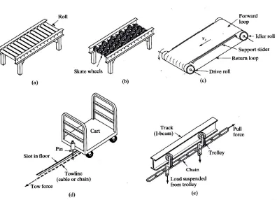
2.2 Types of conveyors
Basically conveyors have many types that designed according to their functions or needs in different industries. For this design project the suitable types of conveyor is belt conveyor. This is because in order to complete a robot pick and place task, the belt itself should be flat which made the belt conveyor most suitable. Figure 2.1 shows the types of conveyors.
Figure 2.1: (a) Roller conveyor, (b) skate-wheel conveyor, (c) belt (flat) conveyor (support frame not shown), (d) in-floor towline conveyor, and (e) overhead trolley
5 2.2.1 Roller conveyor
Consist of tubes (rollers) as shown in Figure 2.1 that are perpendicular to the direction of travel. Rollers attach to fixed frame that moves and this will cause the loads move forward. Both powered and nonpowered are available but due to non-flat surface it is not suitable for pick and place task for robot interface and integration.
2.2.2 Skate-wheel conveyors
Almost same as roller conveyor but it use skate wheels rotating on shafts connect to a frame. Figure 2.1 shows, that this conveyor only suitable to roll pallets, tote pans, and other containers. The application is similar to roller conveyor except the loads must be lighter since the contact between the loads and the conveyor are more concentrated. This conveyor is not considering for this project because of non-flat surface that suitable for pick and place task by robot.
2.2.3 Belt conveyors
6 2.2.4 In-floor towline conveyor
Moving chains or cables powered the four-wheel carts that located in trenches in the floor in industries as shown in Figure 2.1. This conveyor disadvantage is it needs a trench where floor in industries need to be modify in order to make it available. This makes it only suitable for application in manufacturing plants and warehouses.
2.2.5 Overhead trolley conveyor
Wheel carriage running on overhead rail known as trolley in material handling which the loads can be suspended. It consists of multiple trolleys that equally spaced a long a fixed track. It connected together and moved along the track by a chain or cable that forms a complete loop. Generally used in delivery and storage. Any other application is to move parts and assemblies between major production departments.
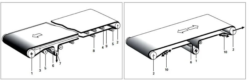
2.3 Belt conveyor components
A belt conveyor consists of a driving pulley, a tail pulley, the tensioning device (if necessary), a conveyor belt and the supporting structure with the belt support (slider bet or carrying roller). Every part of its component is important to make sure the belt conveyor work properly. Driving pulley used to move the conveyor belt that is tensioning between it and tail pulley. Motor used to drive the driving pulley as a power transmission. While the conveyor belt start to move, the supporting structure and belt support act against force from weight or force from product without fail.
7
Figure 2.2: System components in belt conveyor
(Source: <www.habasit.com/en/download.htm#Conveyor_belts>)
Figure 2.3: Sign for system components
(Source: <www.habasit.com/en/download.htm#Conveyor_belts>)
There are two types of simple conveyor that usually used in industry. The left side of Figure 2.2 is Head-driven conveyor and the right side is Centre-driven conveyor. The components are numbered as in Figure 2.2 and Figure 2.3 shows the sign for it:
1. Driving pulley 2. Head or tail pulley 3. Slider belt
4. Carrying roller 5. Snub pulley
6. Deflection roller (idler) 7. Tension pulley
8. Carrying roller (on the return side) 9. Conveyor belt
8
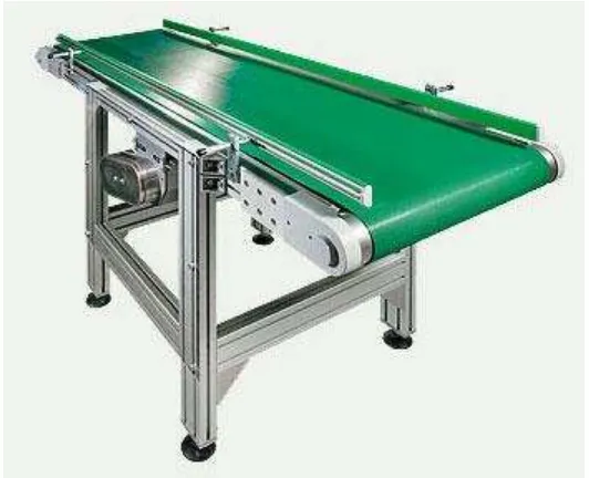
2.4 Support structure
The support structure is part where it must be a rigid, must not distort or flex from the forces it is subjected for example belt tension and the product being move by conveyor. It will be almost impossible to track the conveyor belt if without rigid structure. Besides the supporting structure must be align accurately in all planes. A good conveyor movement must be able to move from one side to another side without interference of any fixed components. So the pulleys or rollers are of sufficient length, and the supporting structure has ample clearance from the belt edges.
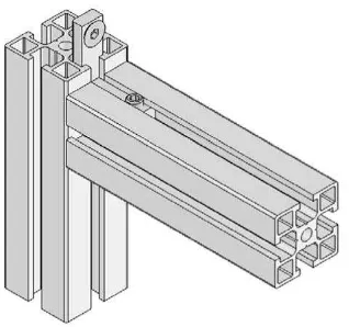
For the material of support structure, the most suitable want in term of cost, weight and reliable is Aluminium alloy profile. Aluminium alloy profile is widely used in industry nowadays. It has a slot and a hole that make it easily to attach with its kind. Figure 2.4 shows the support structure from Aluminium profile with conveyor.
Figure 2.4: Support structure made of Aluminium profile (Source: <http://www.alusic.com/EN/belt_conveyors.htm>)
9
Figure 2.5: Aluminium Profile design (Source: <http://www.aluminiumprofile.com.au/>)
2.5 Pulley and roller fixing
Pulley and roller fixing is the important component or part to ensure the smoothness conveyor belt when it move. Usually, the driving pulley can’t be adjustable and with other rollers and pulleys it should be aligned at the right angle to the belt running axis. Figure 2.6 shows the method of pulleys, rollers and driving pulley mounted. It is important to familiarize with this component in designing belt conveyor.
Figure 2.6: Adjustable bearing, slotted mount and belt conveyor adjustment at head or tail of conveyor