Characterization on Piezoelectric Cantilever for Its Linear Response at
Low Frequency for Measuring Acceleration Level of Vibration
Bong Yu Jing
aand Kok Swee Leong
bFaculty of Electronic and Computer Engineering, Universiti Teknikal Malaysia Melaka, Hang Tuah Jaya, 76100 Durian Tunggal, Melaka, Malaysia
a[email protected], b[email protected]
Keywords: Self-powered, Accelerometer, Resonance, MEMS
Abstract. The output response of the piezoelectric cantilever has excellent linearity over a very wide dynamic range. This paper demonstrates the potential of piezoelectric cantilever to be a self-powered accelerometer. Three different-sized piezoelectric cantilevers were tested under a vibration source at 50 Hz, 100 Hz, and 150 Hz. It is proven that the piezoelectric cantilevers can be used as an accelerometer since the output voltage generated by the cantilever is linear and proportional to the vibration acceleration level far before reaching its resonance. Three piezoelectric cantilevers with similar length of 28.6 mm, but different width of 3.2 mm, 6.3 mm and 12.7 mm were used in the experiment in order to observe the linearity of the output voltage from different-sized piezoelectric cantilevers with the same resonance frequency. The length of piezoelectric may affect the resonance frequency of the cantilever, while the width of the piezoelectric will not. Hence, cantilevers with different width are chosen as the subject of the experiment. The linearity of the experiment results show the maximum error percentage obtained is between 5 to 15% when excited at a vibration magnitude in the range of 1 to 5-g.
Introduction
Vibration energy is available almost everywhere in our daily lives whenever there is moving mechanism. This vibration energy can be transformed into the electrical energy which can be a very useful source to power up small electronics devices, such as wireless sensor node. However, in certain situations, vibration may not be desirable, as this vibration may create damage or disturbance to some structures and even machines. Hence, it is important to study the cause of the vibration and develop solutions to encounter the vibration problem. Vibration magnitude and frequency can be sensed by using an accelerometer, which is an electromechanical device that measures acceleration forces [1]. Various types of accelerometers have been developed, for example capacitive, tunneling, piezoresistive, thermal, resonant and piezoelectric sensing methods [2].
Due to the high sensitivity and ease of fabrication, the capacitive and piezoresistive types of accelerometer [3-6] have been largely applied in the industry. However, piezoresistive accelerometers consume relatively high power in comparison to other micro-system devices. Capacitive accelerometers, on the other hand, require more electronics circuits, which increase its electrical power consumption too [1]. Power consumption has been an important criterion for a micro-system design. In order to develop a sustainable system for environmental-friendly applications, batteries need to be replaced with an energy harvester or micro-generator. The piezoelectric accelerometer, which is a sensor operated without external power source or battery, is a better choice than other technologies if low power consumption is taken into account for the operation of a micro-system.
However, the linearity and operating bandwidth output of the piezoelectric cantilever needs to be justified prior to its application in any vibration measuring system. The piezoelectric cantilever requires a sensitive linear transfer function over large frequency range to ensure the measurement of the acceleration is as accurate as possible. Hence, the experiment is conducted to justify the direct piezoelectric effect of the piezoelectric cantilever to make sure the piezoelectric cantilevers demonstrate excellent linearity over a wide dynamic range. Different-sized piezoelectric cantilevers were used in this experiment to observe its output response respectively. The purpose of using
different size cantilevers is to study whether the sizes influence the characteristics of the piezoelectric cantilever as a sensor.
Piezoelectric Accelerometers
A piezoelectric accelerometer is a transducer that uses the direct piezoelectric effect of the piezoelectric materials of which the mechanical or kinetic energy is transformed into electrical energy. It is usually integrated into mechanical structures, such as cantilevers which can be configured for accurate inertial measurements [1]. When a stress or force is applied on the piezoelectric material, electrical charges will be generated. The transfer function of this measureable electric signal can be obtained by analyzing the frequency response of the piezoelectric cantilever. The transfer function needs to be linear so that the piezoelectric cantilever can be used as an accelerometer. The advantages of using this piezoelectric accelerometer over other accelerometers include its extremely wide dynamic range and frequency range, with low output noise, excellent linearity, high sensitivity, and no requirement of external power [7].
Principle of Piezoelectric Cantilever Operation
When a mechanical force causes a suitably polarized 2-layer element to bend, one layer is compressed and the other is stretched. The charge is developed across each layer in an effort to counteract the imposed strains as shown in Fig. 1 [8].
Fig. 1 Illustration of piezoelectric cantilevers [8].
Experimental Set-up
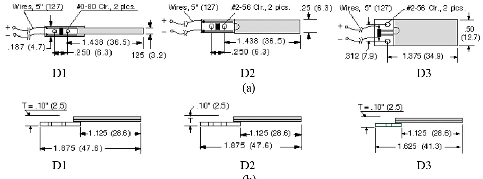
The piezoelectric cantilevers with different widths are shown in Fig. 2. All the three cantilevers have similar effective lengths of 28.6 mm, but different widths of 3.2 mm, 6.3 mm and 12.7 mm, which are named as device D1, D2 and D3 respectively for referencing convenience.
.
D1 D2 D3
(a)
D1 D2 D3
(b)
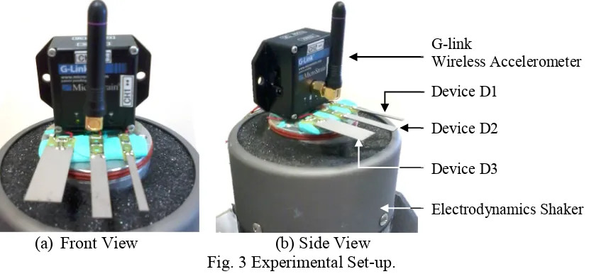
Fig. 3 illustrates the experimental set-up to observe the direct piezoelectric effect of the cantilevers. All three piezoelectric cantilevers were mounted on an electrodynamics shaker. Since the lengths of the cantilevers are similar, their resonance frequencies also are almost similar at 275 Hz.
(a) Front View (b) Side View Fig. 3 Experimental Set-up.
The G-link wireless accelerometer from LORD MicroStrain® was used to measure the g-level of the vibration source. Having determining the g-level, the vibration source can be manipulated and transferred to the piezoelectric cantilever to identify the output response from the piezoelectric cantilevers at different vibrations. The data collected by the G-link wireless accelerometer in time domain was processed using the FFT function of the Matlab application to convert into frequency domain in order to extract the acceleration level (g-level) of the vibration source.
In order to determine the operating frequency range of the piezoelectric cantilevers, the frequency response, in terms of output voltage (Vrms) for the piezoelectric cantilevers, was recorded by exciting the cantilevers with the electrodynamics shaker at a range of frequency from 10 Hz to 350 Hz with the acceleration level (g-level) fixed at constant magnitude 1-g (9.81 m/s2). The frequency response
obtained is as shown in Fig. 4.
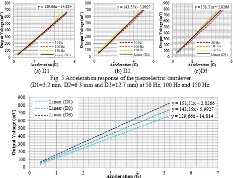
All of the three piezoelectric cantilevers were excited at 50 Hz. The output voltage (Vrms) produced by the piezoelectric cantilevers for acceleration level between 0.5-g to 5-g are recorded as shown in Fig. 5(a). The experiment was repeated with vibration sources of 100 Hz and 150 Hz to observe the effect of different frequencies on the voltage output of the piezoelectric cantilevers. The result is as shown in Fig. 5(b) and Fig. 5(c).
Experimental Results
The output voltage produced by the piezoelectric cantilevers across 10 Hz to 350 Hz is shown in Fig.4. The obtained resonance frequencies, which are around 275 Hz, are similar to the frequencies stated in the Piezo System Inc [9]. The graph illustrates that the output voltages of the piezoelectric cantilevers remain constant at frequencies between 20 Hz to 170 Hz. This frequency range can be used as the operating range of the piezoelectric accelerometer, as variations in frequency will not influence the output voltage produced. The acceleration measurement should be the g-level that will influence the measurement value given by the sensor; the frequency of the vibration source should not have any effect on the measurement. Therefore, subsequent acceleration response was set within the operating frequency of 50 to 150 Hz.
G-link
Wireless Accelerometer Device D1
Device D2
Device D3
Fig. 4 Frequency response of the different sized piezoelectric cantilever.
Since the operating frequency range is between 20 Hz to 170 Hz, the vibration source with 3 different frequencies (50 Hz, 100 Hz, and 150 Hz) allocated in the operating frequency range are selected as the test subject for the piezoelectric cantilevers. The linearity result obtained is shown in Fig.5. It shows that the piezoelectric cantilevers do have excellent linearity in response to the acceleration. The combined overall results shown in Fig.6 show that the piezoelectric cantilever with a larger size has a higher sensitivity.
(a) D1 (b) D2 (c)D3 Fig. 5 Acceleration response of the piezoelectric cantilever
(D1=3.2 mm, D2=6.3 mm and D3=12.7 mm) at 50 Hz, 100 Hz and 150 Hz.
Fig. 6 Acceleration average linear transfer function graph for piezoelectric cantilever with different cantilever widths of D1=3.2 mm, D2=6.3 mm and D3=12.7 mm
Conclusion
The average transfer function obtained for D1 piezoelectric cantilever is = 129.66 − 14.814
with maximum 15% percentage error compared to the actual output voltage of the piezoelectric cantilever for the acceleration between 1-g to 5-g. While for the D2 piezoelectric cantilever, the linear equation obtained is = 143.35 − 5.9927 with maximum 5% percentage error. Similarly, the linear equation obtained for D3 piezoelectric cantilever is = 158.51 + 2.0266 with maximum 15% percentage error. The result also shows that the piezoelectric cantilever with a larger size has a higher sensitivity. Overall, the result proves that the piezoelectric cantilevers do have excellent linearity over a wide dynamic range, which allows the piezoelectric cantilever to be used as a device to measure acceleration. This piezoelectric cantilever type of accelerometer can be a useful vibration measuring tool in automobile, biomedical, electronics, and even structural industry for a sustainable electronic system, with minimal maintenance since no external power source is needed.
Acknowledgment
The authors would like to thank the Ministry of Higher Education for the research grant, PRGS/2011/FKEKK/TK02/1 – T00001, as well as Universiti Teknikal Malaysia Melaka (UTeM) for providing the CoE short term research grant PJP/2012/CeTRI/Y00001; Advanced Sensors and Embedded Control Research Group and Centre for Telecommunication Research and Innovation for supporting the research and sponsoring the presentation of this article.
References
[1] A. Dastidar, Piezoelectric MEMS Accelerometer: A Case Study, AICTE Sponsored National Seminar on Nanosensors & Applications (NSNA-2013), pp. 28-34, Oct 2013.
[2] Q. Zou, E.S. Kim, G.E. Loeb, Single and triaxis piezoelectric bimorph accelerometers, J. Microelectromech. Syst. 17 (2008) 45-58.
[3] W. Jiangfeng, (2002) Sensing And Control Electronics for Low-Mass Low-Capacitance MEMS Accelerometers (PhD Thesis), Carnegie Mellon University.
[4] B.V. Amini, S. Pourkamali, A. Farrokh, “A High Resolution, Stictionless, Cmos Compatible Soi Accelerometer with a Low Noise, Low Power, 0.25µm CMOS Interface”, 17th IEEE International
Conference on Micro Electro Mechanical Systems, pp 572-575, Jan 2004.
[5] V. Agarwal, T.K. Bhattacharayya, S. Banik, Design steps for bulk micro machined single axis silicon capacitive accelerometer with optimised device dimensions, J. Phy.: Conference Series. 34 (2006) 722–727.
[6] E.J. Eklund, A.M. Shkel, Single-mask fabrication of high-g piezoresistive accelerometers with extended temperature Range, J. Micromec. Microeng. 17 (2007) 730-736.
[7] M. Serridge, T. R. Licht, Piezoelectric Accelerometer and Vibration Preamplifier Handbook, Bruel & Kier, Nærum, Denmark, 1987.