CHAPTER 1
INTRODUCTION
1.1. General View
Conventional structures are built to withstand loads by relying on
their own strength which comes from the materials that are used.
To resist bigger load, the structure will have to be designed with
higher ductility and strength. One consequence is to increase the
dimension of the structure, which will also impose bigger load on
the structure. As such, the structure will have limited performance.
Moreover, the material used alone will not be sufficient to provide
the desired damping properties to the structure.
The performance of the structure can be increased in many
ways. One of the available methods is by applying control systems.
In this case, devices will be installed to the structure. These devices
will exert forces to the structure as they response to the changes
sensed from structural motion and ground motion when needed.
Various control systems are introduced to improve the
properties of the structure to overcome this problem. The systems
will modify the response of the structure dynamically in a desirable
manner. The systems are expected to adjust themselves to the
systems. A system might consist of sensors and control devices
implementing an algorithm to reduce the effects of the environment
to the structure. Many of these systems have been considered by
researchers and their implementations in field shows that this
concept is a promising way to protect structures from wind and
seismic excitations.
1.2. Benchmark Problem
A benchmark problem based on the Missouri 74–Illinois 146
cable-stayed bridge spanning the Mississippi River near Cape Girardeau,
Missouri, designed by the HNTB Corporation (Hague, 1997) named
Bill Emerson Memorial Bridge has been proposed by Dyke et al
(2002). The objective of this benchmark problem is to compare the
performances of several control systems. A three-dimensional
bridge model created based on detailed drawings of the bridge to
represent the behavior of the full scale benchmark bridge.
Researchers are invited to apply various algorithms, devices, and
sensors to the model. Their performances will be assessed based
on several criteria that have been identified as critical to the
1.3. Overview of The Bridge of Cape Girardeau
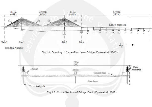
The longitudinal section of the bridge can be seen in Fig. 1.1. The
cable-stayed bridge of Cape Girardeau is composed of two towers,
128 cables, and 12 additional piers in the approach bridge from the
Illinois side. It has a total length of 1205.8 m (3956 ft). The main
span is 350.6 m (1150 ft) in length, the side spans are 142.7 m (468
ft) in length, and the approach on the Illinois side is 570 m (1870 ft).
(Dyke et al, 2002)
A cross section of the deck is shown in Fig. 1.2. The bridge has
four lanes plus two narrower bicycle lanes, for a total width of 29.3
m (96 ft). Additionally, a concrete barrier is located in the center of
the bridge, and a railing is located along the edges of the deck.
The deck is composed of steel beams and prestressed concrete
slabs. The reinforcement steel ASTM A709 grade 50W is used, with
an ݂௬ of 344 MPa (50 ksi). The concrete slabs are made of
prestressed concrete with an ݂’ of 41.36 MPa (6000 psi). The 128
cables are made of high–strength, low–relaxation steel (ASTM
A882 grade 270). The smallest cable area is 28.5 cm2 (4.41 in2)
and the largest cable area is 76.3 cm2 (11.83 in2). The cables are
covered with a polyethylene piping to resist corrosion. The
H-shaped towers have a height of 102.4 m (336 ft) at pier 2 and 108.5
towers are constructed of reinforced concrete with ݂’ of 37.92 MPa
(5.5 ksi).
The cross section of each tower varies five times over the height
of the tower, as shown in Fig. 1.3. Section A is used in the top of
the legs, section B in the middle of the legs, and section E in the
bottom of the towers. Some of these elements have variable
sections. Section D shows the cross section in the bottom strut, and
section C shows the cross section of the strut located in the middle
of the tower. The approach bridge from the Illinois side is supported
by 11 piers and bent 15 which are made of concrete. The deck
consists of a rigid diaphragm made of steel with a slab of concrete
at the top. The densities of the materials as specified in the
drawings are summarized in Table 1.1.
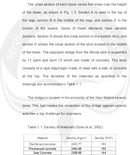
The bridge in located in the proximity of the New Madrid seismic
zone. This fact makes the protection of the bridge against seismic
[image:4.612.94.517.170.675.2]activities a big challenge for engineers.
Table 1.1: Density of Materials (Dyke et al, 2002)
Material Density (Kg/m3) Density (PCF)
Reinforced concrete 2402.77 150
Prestressed concrete 2482.86 155
Seal Concrete 2306.66 144
Stay cable grout 2322.68 145
F
Fig 1.1. Drawin
Fig 1.2. Cro
ng of Cape Gira
oss-Section of
ardeau Bridge
f Bridge Deck (
(Dyke et al, 2
(Dyke et al, 20 002)
1.4. Prob
The
of s
grou direc bridg Fig blem Limita foundation soil–structu und accele
ction is con
ges. (Dyke
g 1.3. Towe
ations
n of the brid
re interact
ration is a
nsidered to
et al, 2002
r Cross-sec
dge is attac
ion can be
applied in t
o be the m
)
ction (Dyke
ched to bed
e neglecte
the longitu
ost destruc
e et al, 2002
drock, so t
ed. One-dim
dinal direc
ctive in cab 2)
he effects
mensional
ction. This