UNIVERSITI TEKNIKAL MALAYSIA MELAKA
STUDY THE SURFACE ROUGHNESS OF AISI 1045 CARBON
STEEL BY USING DRY CNC TURNING
This report is submitted in accordance with the requirement of Universiti Teknikal Malaysia Melaka (UTeM) for the Bachelor of Manufacturing Engineering
Technology (Process and Technology) with Honours
by
NORZARATUL AIN BINTI ISMAIL B071210103
930513-02-5248
UNIVERSITI TEKNIKAL MALAYSIA MELAKA
BORANG PENGESAHAN STATUS LAPORAN PROJEK SARJANA MUDA
TAJUK: Study the Surface Roughness of AISI 1045 Carbon Steel by Using Dry CNC Turning
SESI PENGAJIAN: 2015/16 Semester 1
Saya NORZARATUL AIN BINTI ISMAIL
mengaku membenarkan Laporan PSM ini disimpan di Perpustakaan Universiti Teknikal Malaysia Melaka (UTeM) dengan syarat-syarat kegunaan seperti berikut:
1. Laporan PSM adalah hak milik Universiti Teknikal Malaysia Melaka dan penulis. 2. Perpustakaan Universiti Teknikal Malaysia Melaka dibenarkan membuat salinan
untuk tujuan pengajian sahaja dengan izin penulis.
3. Perpustakaan dibenarkan membuat salinan laporan PSM ini sebagai bahan pertukaran antara institusi pengajian tinggi. atau kepentingan Malaysia sebagaimana yang termaktub dalam AKTA RAHSIA RASMI 1972)
(Mengandungi maklumat TERHAD yang telah ditentukan oleh organisasi/badan di mana penyelidikan dijalankan)
__________________________
DECLARATION
I hereby, declared this report entitled “Study the Surface Roughness of AISI 1045 Carbon Steel by Using Dry CNC Turning” is the results of my own research except
as cited in references.
Signature :………
Name : NORZARATUL AIN BINTI ISMAIL
v
APPROVAL
This report is submitted to the Faculty of Engineering Technology of UTeM as a partial fulfillment of the requirements for the degree of Bachelor of Manufacturing Engineering Technology (Process and Technology) with Honours. The member of the supervisory is as follow:
………. DR. UMAR AL-AMANI BIN HJ. AZLAN
vi
ABSTRACT
vii
ABSTRAK
viii
DEDICATIONS
ix
ACKNOWLEDGMENT
I wish to acknowledge and express my gratitude and appreciation to my supervisor, Dr. Umar Al-Amani bin Hj. Azlan for his supervision, encouragement, suggestion and constant support through the research and contribution for the success of this project. My deepest gratitude and special thanks also goes to my beloved parents, Ismail bin Kassim and Siti Maizun bt Sebran, my sister and my brother for their endless love and special support.
Sincere thanks to Mr. Nor Fauzi bin Tamin and Dr. Mohd Hadzley bin Abu Bakar from faculty of Manufacturing Engineering (FKP) for helping me to solve various experiment problems and to finish the project. Besides that, also thanks to every assistant engineers in Faculty of Engineering Technology (FTK) for their cooperation and active involvement.
x
TABLE OF CONTENTS
DECLARATION ... iv
APPROVAL ... v
ABSTRACT ... vi
ABSTRAK ... vii
DEDICATIONS ... viii
ACKNOWLEDGMENT ... ix
TABLE OF CONTENTS ... x
LIST OF FIGURES ... xiii
LIST OF TABLES ... xiv
LIST OF SYMBOLS AND ABBREVIATIONS ... xv
CHAPTER 1 ... 16
1.1 Project Background ... 16
1.2 Problem Statement ... 17
1.3 Objective ... 18
1.4 Project Scope ... 18
1.5 Concluding Remarks ... 19
CHAPTER 2 ... 20
2.1 Turning Process ... 20
xi
2.2 Machining Parameters ... 23
2.2.1 Spindle Speed ... 24
2.2.2 Feed Rate ... 25
2.3 Cutting Tool ... 25
2.3.1 Cutting Tool Material ... 26
2.3.2 Cutting Tool Wear... 27
2.4 Chips Formation ... 28
2.5 Dry Cutting ... 29
2.6 Carbon Steel ... 30
2.6.1 Carbon Steel Properties ... 33
2.6.2 Limitation of Carbon Steel ... 34
2.7 Surface Roughness ... 34
2.7.1 Surface Roughness Parameters ... 35
2.8 Measurement of Surface Roughness ... 36
2.8.1 Surface Roughness Tester ... 36
2.8.2 Optical Microscope ... 37
2.9 Concluding Remarks ... 38
CHAPTER 3 ... 39
3.1 Experimental Design ... 39
3.2 Performing the Experiment ... 39
3.2.1 Material and Cutting Tool Preparation ... 39
xii
3.3 Parameter Study ... 43
3.3.1 Effect of Different Spindle Speed ... 44
3.3.2 Effect of Different Feed Rate ... 44
3.4 Sample Output Preparation ... 44
3.5 Analysis of Data ... 45
3.5.1 Surface Roughness Tester ... 45
3.5.2 Observation of Tool Wear by Optical Microscope ... 47
3.6 Concluding Remarks ... 48
CHAPTER 4 ... 49
4.1 Surface Roughness ... 49
4.1.1 Surface Roughness Data and Graph Analysis ... 49
4.2 Tool Wear ... 54
4.3 Chips Formation ... 59
4.4 Concluding Remarks ... 62
CHAPTER 5 ... 63
5.1 Conclusion ... 63
5.2 Recommendation ... 64
xiii
LIST OF FIGURES
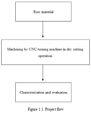
Figure 1.1: Project flow... 19
Figure 2.1: Conventional turning machine ... 20
Figure 2.2: Turning process ... 21
Figure 2.3: CNC turning machine ... 23
Figure 2.4: Parameters that affect surface roughness... 24
Figure 2.5: Turning cutting insert ... 26
Figure 2.6: Tool wear zone ... 28
Figure 2.7: Type of chips formation ... 29
Figure 2.8: Classification of steel ... 31
Figure 2.9: Cross-section typical surface of roughness average (Ra) ... 36
Figure 2.10: Schematic diagram for stylus tester instrument ... 37
Figure 2.11: Optical microscope ... 38
Figure 3.1: Overall of the experimental design of the project ... 40
Figure 3.2: AISI 1045 Carbon Steel ... 41
Figure 3.3: Carbide insert type ZP352 ... 41
Figure 3.4: Insert holder ... 41
Figure 3.5: Centre drilling process ... 42
Figure 3.6: CNC turning machine DMG Mori Seiki CTX 310 ecoline ... 42
Figure 3.7: Clamped workpiece ... 42
Figure 3.8: Workpiece after turning process ... 45
Figure 3.9: Number of experiment marks on workpiece ... 45
Figure 3.10: Surface roughness tester of Mitutoyo Surftest SJ-401. ... 46
Figure 3.11: The uses of stylus at the contact surface of workpiece... 47
Figure 3.12: Optical microscope in Metrology Laboratory ... 47
Figure 3.13: Observation of tool wears ... 48
Figure 4.1: Ra profile of AISI 1045 carbon steel at feed rate 0.15 mm/rev... 50
Figure 4.2: Ra profile of AISI 1045 carbon steel at feed rate 0.50 mm/rev... 51
Figure 4.3: Surface roughness vs. Spindle speed at feed rate 0.15 mm/rev ... 52
Figure 4.4: Surface roughness vs. Spindle speed at feed rate 0.50 mm/rev ... 53
Figure 4.5: Tool wear vs. Spindle speed at feed rate 0.15 mm/rev ... 55
Figure 4.6: Tool wear vs. Spindle speed at feed rate 0.50 mm/rev ... 56
Figure 4.7: Tool wear on carbide inserts at feed rate 0.15 mm/rev ... 57
Figure 4.8: Tool wear on carbide inserts at feed rate 0.50 mm/rev ... 58
Figure 4.9: Formation of chips at feed rate 0.15 mm/rev... 60
xiv
LIST OF TABLES
Table 2.1: Composition of plain carbon steel ... 32
Table 3.1: Dry cutting process variables ... 43
Table 3.2: General information of surface roughness tester ... 46
Table 3.3: General information of optical microscope ... 48
Table 4.1: Overall of Ra value of AISI 1045 carbon steel ... 49
Table 4.2: Spindle speed and Surface Roughness, Ra at feed rate 0.15 mm/rev ... 52
Table 4.3: Spindle speed and Surface Roughness, Ra at feed rate 0.50 mm/rev ... 53
Table 4.4: Spindle speed and tool wear value at feed rate 0.15 mm/rev... 55
xv
LIST OF SYMBOLS AND ABBREVIATIONS
BUE - Build-up Edge
CNC - Computer Numerical Control CAD - Computer Aided Design
CAM - Computer Aided Manufacturing CLDATA - Cutter location data
HSS - High Speed Steel NC - Numerical Control
Ra - Roughness Average
Rq - Root-mean-square roughness
Ry - maximum peak-to-valley roughness height AA - Arithmetic Average
CLA - Center Line Average 3D - Three Dimensional
AISI - American Iron and Steel Institute SS - Stainless Steel
Mpa - Mega Pascal
Rpm - Revolutions per minute
UTeM - Universiti Teknikal Malaysia Melaka
μ - Micron
16
CHAPTER 1
INTRODUCTION
1.1 Project Background
Machining is an industrial process in which metal parts are shaped or removed by metal cutting process (Patel et al., 2012). In the metal removal process, the output quality of the machined part is rather important. Turning is one of the widely used and important machining processes in engineering industries (Ahilan et al., 2013). Lathe machine is one of oldest conventional machine tool that still being used in the manufacturing industries to produce cylindrical parts. However, Computer Numerical Control (CNC) turning machine are widely used nowadays as it can produce good quality machined parts, high accuracy and high productivity (Patel et al., 2012).
Turning is machining operation that can be performed on a lathe and widely used in variety manufacturing industries such as automotive and aerospace. In the machining process, quality of surface plays a very important role in the performance of turning. This is because, good quality turned surface is significant in improving quality (Patel et al., 2012). In CNC turning, there are many parameters cutting conditions that will affect the surface roughness of the workpiece. These factors are controllable factors such as feed rate, depth of cut and spindle speed and the uncontrolled factors such as material properties and tool geometry of both tool and workpiece) (Rao et al., 2013).
17 process employed to create the surface.
Although machined surface appear smooth to the naked eye, the surface are quite rough at the microscopic level. In this challenge world, striving for lower cost solution and shorter lead time is the main challenge for industries around the world to maintain their competitiveness. Automated and flexible manufacturing systems are employed for that purpose.
1.2 Problem Statement
Nowadays, the so called surface roughness of the product is a major issue in many industries. The major issue of this factor makes manufacturing engineers faced with the difficulties to increase the productivity (Rawangwong et al., 2014). The demand for high quality products with good surface finish also increase day by day due to the newer applications in various fields such as die and mold manufacturing, automobile and also aircraft industries.
In CNC machining, the optimal parameters and cutting condition under the given machining situation is difficult to determine. The conventional ways to choose the ideal parameters are based upon data from the machining handbooks or from the knowledge of the programmer. Hence, uneven surface roughness is produced because of such conservative machining parameters.
18
lubricant cost and workpiece, and also the tool machine cleaning cycle time. Health problem can be caused by the long term exposure to the cutting fluids and by the inappropriate way while handling with the cutting fluids. Then, the adhesion and friction between tool and chip tend to be higher in dry machining process. These situations will cause higher temperature, higher tool wear rates and consequently, shorter too lives. Therefore, the ideal parameters have to be found in order to achieve the desired surface roughness.
1.3 Objective
The objectives of this project are:
i. To study the effect of spindle speed and feed rate of dry cutting CNC turning on surface roughness of AISI 1045 carbon steel.
ii. To identify the optimum spindle speed and feed rate based on characterization study.
1.4 Project Scope
19
Figure 1.1: Project flow
1.5 Concluding Remarks
20
CHAPTER 2
LITERATURE REVIEW
2.1 Turning Process
Turning is one of the most important and widely used machining operations, which is carried out on lathe (Kumar et al., 2012). Turning is a form of machining that is a material removal process and can create variety of features and produces smooth finish on cylindrical surfaces (Saini et al., 2014). The removal material process of turning is by a relative motion between a single point of cutting tool and rotating cylindrical workpiece. In a direction that is parallel to the axis of rotation, the cutting tool will fed linearly on the workpiece (Quazi et al., 2013). Figure 2.1 shows the conventional turning machine that can be used for turning process
Figure 2.1: Conventional turning machine (Faizal, 2010)
21
operation of an external surface with the rotating workpiece, a single point cutting tool and cutting tool that feeding parallel to the axis of the workpiece. A lathe table is needed to perform turning process in which the tool is stationary and the part is rotated. The fixture on a lathe table are made to secure the workpiece, and able to rotate at high speeds. The schematic diagram of turning process can be shown as in Figure 2.2.
Figure 2.2: Turning process (Hou, 2012)
Typically, part that have many features such as holes, grooves, threads, tapers, variation diameter steps and even contoured surface can be produced by turning process. However, parts that are used in limited quantities, perhaps for prototypes such as shafts and fasteners are parts that are completely fabricated through turning (Jayesh et al., 2014).
22
Nowadays, Computer Numerical Controlled (CNC) machines are widely used in every manufacturing processes. All the functions like tool offset and tool compensation, program editing capability, program storage and various degree of computation can be found with CNC machine (Patel et al., 2012). Besides that, CNC machine has the ability to send and receive data from a various sources and easily realized the remote locations through on board computer. In industries, automated and flexible manufacturing systems are employed to manufacture low cost and high quality product in short time due to the high accuracy and low processing time of CNC machine (Bernandos and Vosniakos, 2002).
CNC turning is a specific form of CNC machining. It rapidly replaced the conventional turning machine such as multi spindle machine and turret machine due to their ease of setting, operation, repeatability and accuracy (Jayesh et al., 2014). CNC turning machine were designed to use modern processes. CNC turning machine can be shown as in Figure 2.3.
2.1.2 Simulation of Turning Process by CNC Machine
In order to simulate the turning process of material removal at a workpiece by CNC machine, a real Computer Aided Design (CAD) has been used. The CAD of material removal simulation gives a close to reality simulation of the real execute Numerical Control program. Before highly complex workpiece being manufactured on CNC machine tool, the manufacturing process need to be checked before proceed to the real machine tool. Most of the Numerical Control (NC) programs are created via Computer Aided Manufacturing (CAM) tools. The software only considers the workpiece and the tools ( Klimant et al., 2014).
23
CLDATA file into the machine while the CNC specific the G-code, which is the NC program.
Figure 2.3: CNC turning machine
2.2 Machining Parameters
In turning process, parameters are the main factors to increase the productivity of the machining process. Higher values of cutting parameters offered big opportunities for increasing the productivity but also takes part in the greater risk of deterioration in surface quality and tool life (Yadav et al., 2012). The parameters that involved in the machining of turning were also the same with parameters of different machining process like milling and drilling.
24
Figure 2.4: Parameters that affect surface roughness (Bernandos and Vosniakos, 2002)
Trial and error method was popular among the workers to find the most appropriate cutting condition .The quality of the mating parts plays an important role performance and wear of the mating parts wherever two machined surface came in contact with one and other. A number of factors such as machining variables like cutting speed, depth of cut, feed rate cutting tool wears and other parameters were the main factors of the surface irregularities in machining processes (Harish et al., 2013).
2.2.1 Spindle Speed
25 preferred (Oguz et al., 2007).
2.2.2 Feed Rate
The situation when the cutting tool (feed) travelling in millimetres per each spindle revolution is the feed rate of turning process (Azza, 2013). Feed rate shows how fast the turning tool moves through the material being cut. It is directly related to the spindle speed and expressed in millimetres per revolution [mm/rev]. Feed rate will decrease with dull tools, a lack of coolant or deep cuts (Syahmi, 2012). Feed rate is the most influential parameter when other parameters are constant. As the tool diameter and spindle speed increase, the surface roughness also increases linearly. This is because and increasing relation exists between the feed rate and the surface roughness.
By statistical method, it is found that feed rate and machining timcontributed significantly to surface roughness. Within the same machining time, a higher feed rate would not degrading surface quality and tool life significantly (Kiswanto et al., 2014). Thus, smooth surface will produce with the lower feed rate. Karabulut (2015) from his research stated that the feed rate has the highest effect on the surface roughness right after the depth of cut and the cutting speed respectively.
2.3 Cutting Tool
In turning process, a single point tool always being used as the cutting tool. Single point tool is a tool that has one cutting edge to remove material from the workpiece. Different machining applications used different cutting tool materials (Azza, 2013). In order to produce good quality parts, cutting tool that was made by harder material than the workpiece material should be used to cut the material.