UNIVERSITI TEKNIKAL MALAYSIA MELAKA
Design and Development of Semi-Auto
Point-To-Point Pneumatic Tube System for Manufacturing
Applications
Thesis submitted in accordance with the partial requirements of the Universiti Teknikal Malaysia Melaka
Bachelor of Manufacturing Engineering (Robotic and Automation)
By
MD NOR IRWAN SHAH BIN MD AB RAHIM
APPROVAL
This thesis submitted to the senate of UTeM and has been accepted as partial fulfillment of the requirements for the degree of Bachelor of Manufacturing Engineering (Manufacturing Robotic and Automation). The members of the supervisory committee
are as follow:
………. Supervisor
En Hassan Attan
DECLARATION
I hereby, declare this thesis entitled “Design and Develop Of Semi-Auto Point to Point Pneumatic Tube System for Manufacturing Applications” is the results of my own
Project except as cited in the reference.
Signature : ………..
Author’s Name : ………..
ABSTRACT
DEDICATION
1 dedicate this PSM thesis to my beloved father, Md Ab Rahim Harun.
ACKNOWLEDGEMENTS
Bismillahirrahmanirrahim. Alhamdullillah, with the helps and blessings from Allah S.W.T., I managed to complete this project succesfully. First of all, I would like to thank my parents, for their concern and support, all over the time. Not forgotten my brothers and sister, who had helps me a lot supporting me physically and morally.
I also want to thank Mr. Hassan Attan from Manufacturing Engineering Faculty, Universiti Teknikal Malaysia Melaka, for supervised me all along this project, and provide helps, guides, ideas, and suggestions to accomplish this project. All the supports and motivation that been given to me are greatly appreciated.
Also not forgotten, IR. Wan Azman Wan Abdullah from Radicare (M) Sdn Bhd, for giving a permission to visited about the PTS at the Radicare (M) Sdn, Bhd, and also Mr. Pauzi Awang from Machanical Department for the assistance during the Project.
With a deep sense of gratitude, I would also like to express my sincere thanks to my colleague, Noorul Mannan, Sairizal Misri, Faizul and Muhammad Zhafran for the helps and supports that been shown by them.
TABLE OF CONTENTS
Abstract………..…………..…….…….….i
Dedication………..…..……….…….ii
Acknowledgements………..…..………..….iii
Table of Contents ………..…..……….iv
List of Tables ………..…………..………....ix
List of Figures ………...…….…....x
Sign and Symbols ………...………….…...xiii
List of Appendices ………..………xiv
1. INTRODUCTION……….………..….1
1.1 Introduction………..……1
1.2 Objectives ………..….2
1.3 Scope of Project………..……….2
1.4 Problem Statements……….………2
2. LITERATURES REVIEW………..3
2.1 History of PTS ………...…..3
2.2 Profitability………..….6
2.2.1 Why PTS?………..6
2.2.2 Who needs PTS?……….………..7
2.3 Components and System in PTS ………….……….…………..…7
2.4 Stations …….………..…8
2.4.1 Type of Station PTS…..….………..8
2.4.2 Slide Sleeve Station….……...………...9
2.4.3 EWS Station..……….…….10
2.4.4 Premium Station………..………....11
2.4.6 The Desk Station….………..………..14
2.4.7 Mega Station………...………...15
2.4.8 KSA Station…..……….….…17
2.4.9 Load Station..………...18
2.5 Station Control Panels….……….……..19
2.6 Carriers….………...…...20
2.7 Control Center System…..……….…21
2.8 PTS Transmission Riser…..……….….22
2.9 Blower…..………..……23
2.9.1 Single-phase Blower WSVR-11……….…24
2.9.2 Single-phase Blower WSVR-12……….…24
2.9.3 Three-phase Blower………25
2.9.4 Blower Control System…...…….………...27
2.10 Transfer Unit ...………..……27
2.11 Tubing……….28
2.12 Application of PTS………..……29
2.12.1 Administrations……….…..29
2.10.1.1 The Area of Application…………...……….29
2.10.1.2 The Transport Load………..……….…30
2.10.1.3 The System at Administrator System………..………..30
2.10.1.4 The Automatic Station………..……….…31
2.10.1.5 The Mail Station………..……….…..31
2.10.1.6 The Administration-Specific Demands:…………..…...….…..32
2.12.2 Bank………...……….….32
2.12.2.1 The Area of Application………...……….33
2.12.2.2 The Transport Load………..………….….…33
2.12.2.3 The Drive-Up Teller Window Bank’s System….….……..…..33
2.12.2.4 The Central Money Depot……….….…….…..34
2.12.3 Counters………..….35
2.12.3.2 The Area of Application………..………..….…...36
2.12.3.3 The Systems that using in Counters……….….….…...….37
2.10.3.3.1 The Uni-Directional………..…….……….37
2.10.3.3.2 The Uni-Directional System with PC……… …37
2.10.3.3.3 The Bi-Directional System……….…....38
2.12.4 Industrial Operations………....39
2.12.4.1 The Advantages………..………40
2.12.4.2 The Area of Application…………...……….….40
2.12.4.3 The Transport Load………..………..…40
2.12.4.4 The Systems That Using in Industrial………..………..40
a) The Fully Automatic System……….….40
b) The Diverter System………..…..41
c) Steel Samples System………..42
2.12.5 Pharmaceutical………..…...42
2.12.5.1 The System in Building for Pharmaceutical………...43
2.12.5.2 The Storage Area in Pharmaceutical……...………...44
2.12.5.3 The Dispensary in Pharmaceutical……..….……….45
2.12.6 Hospitals……….….45
2.12.6.1 The Advantages……….46
2.12.6.2 The Area of Application………46
2.12.6.3 The Transport Load………...47
2.12.6.4 The System in Building for Hospital………47
2.12.6.5 The Laboratory Station in Hospital………...48
2.12.6.6 The Automatic Station PTS in Hospital……….48
2.12.6.7 Specific Demands of a Hospital………....49
2.13 Benefit of PTS..………50
3. METHODOLOGY………51
3.2 Project Analysis………..……...53
3.3 Selection Method for Design Selection………...……...53
3.4 Design Conceptual………..53
3.4.1 Conceptual Design 1st for semi-auto Point-To-Point PTS….…….56
3.4.2 Conceptual Design 2nd for semi-auto Point-To-Point PTS………..57
3.4.3 Conceptual Design 3rd for semi-auto Point-To-Point PTS………..58
3.4.4 Selecting Design………..………....59
3.6 Component Selection………...………...59
3.6.1 Selecting Tubing and Material………..…..…60
3.6.2 Comparison Method………..………..………62
3.6.3 Cost Estimate Method..……….………..………64
3.6.4 Other Advantages………..……..64
3.7 Selecting Blower………...……….65
3.7.1 Comparison Method………..……...65
3.7.2 Cost Estimate Method……….67
3.8 Selecting Station………..……..69
3.8.1 Compare Method……….……..….69
3.8.2 Cost Estimate Method……….71
3.9 Selecting Carrier………....71
3.9.1 Comparison……….72
3.9.2 Cost Estimate………..72
3.10 Develop the Prototype ………..…..72
4. RESULT………..………...76
4.1 Bill of material………78
4.1.1 Bill of material (BOM)………79
4.1.2 Cost Estimate………..……79
6. SUMMARY AND CONCLUSION………...85
7. FUTURE WORK………86
REFERENCES….……….………..…...87
APPENDICES
A Technical Data B Diagram and Table
C Dimension for components D Calculation
LIST OF TABLES
2.1 Features for Three-Phase Blower 26
3.1 Comparison Method 59
3.3 Specifications for PVC Tubing 61
4.1 Bill of Material that are used in Semi-Auto Point to Point PTS 79
LIST OF FIGURES
2.1 A pneumatic tube table, Central Telegraph Office,
London, during the 1930s (MacGregor, J, 1930s) 3 2.2 The automatic switch room for the London Street
Tube System (MacGregor, J, 1930s) 5
2.14 Control Center System Software 21
2.15 Transmission Riser 22
2.16 Blower 23
2.17 Single-phase Blower WSVR-11 24
2.18 Single-phase Blower WSVR-12 25
2.19 Three-phase Blower 26
2.20 Blower Control System 27
2.21 Diverter 28
2.22 PVC Tubing 29
2.23 A System in Building 30
2.24 Mail Station 31
2.25(b) Drive-up teller window with video system 34
2.26(a) Central money depot 34
2.26(b) Control center in the lobby 35
2.27 Counters with PTS 36
2.28 Uni-Directional System 37
2.29(a) Uni-Directional System with PC 38
2.29(b) Monitoring System 38
2.30 Bi-Directional System 38
2.31 Change station 39
2.32 Fully Automatic System, and Automatic Loading and
Unloading Sttion 41
2.33 Diverter System 41
2.34 PTS for Steel Samples system 42
2.35 Sales area in a conventional pharmacy compared with a pharmacy
using the PTS 43
2.36 PTS in Building for pharmaceutical 44 2.37 The station at the separate drawer storage area 44 2.38 Double medical counter with a central technical unit for the PTS,
EDP and cash desk 45
2.39 Nurse´s desk with automatic station 46
2.40 System in Building 47
2.41 The Laboratory and the Laboratory PTS Station 48 2.42 Automatic stations with varying applications 49 3.1 Basic conceptual designs for Point-To-Point PTS 55 3.2 1st Design Conceptual for semi-auto Point-To-Point PTS 56 3.3 2nd Design Conceptual for semi-auto Point-To-Point PTS 57 3.4 3rd Design conceptual for semi-auto Point-To-Point PTS 58
3.5 PVC Tubing 60
3.8 Versatility (Busada Manufacturing Corporation ®, 2005) 63
3.9 Single-phase Blower WSVR-12 65
3.10 Slide Sleeve Station 70
3.11 Rohrpostsysteme carrier 71
LIST OF ABBREVIATIONS, SYMBOLS, SPECIALIZED
NOMENCLATURE
UTeM - Universiti Teknikal Malaysia Melaka PCP - Pneumatic Capsule Pipeline
PTS - Pneumatic Tube System PVC - Polyvinyl Chloride PSM - Projek Sarjana Muda
LIST OF APPENDICES
Appendices A
Technical Data for Pneumatic Tube Systems Technical Data of PVC Tubing and Material Technical Data of Zinc-Coated Galvanized Steel Technical Data of Aluminum Tubing and Material Additional Typical Material Properties for PVC Tubing Special Bending for Tubing
Technical Data for Carrier
Features and Technical Data for Three Phase Blower
Appendices B
Moody’s diagram
Table for Resistant Coefficients for Valve and Fitting
Appendices C
Components that have been using in this Project
Appendices D
Calculation A Calculation B
Appendices E
CHAPTER 1
INTRODUCTION
1.1 Introduction
Pneumatic Tube System (PTS), also known as Pneumatic Capsule Pipelines (PCP), is a system in which cylindrical containers are propelled through a network of tubes by compressed air or by vacuum. They are used for transporting physical objects. PTS, also known as a conveying system used for transporting material within or between buildings. It function using compressed air or by vacuum to move the material using a carrier.
Pneumatic Tube Systems are used broadly in the world especially in developed countries. The pneumatic tube systems are applied in various industries in developed countries. In Malaysia, the Pneumatic Tube System is applied in almost all general and private Hospital in several states in the country. Other application of pneumatic tube systems are in Hospital, Supermarket, Pharmaceutical, Industrials, Banks, Administration and offices.
1.2 Objective
The objective of this project is to design and develop the PTS for manufacturing applications. This will also is to automate the document transferring process. The design process will look into reducing the cost of PTS. The design will also explore the usage of PTS by implementing at UTeM FKP laboratory.
1.3 Scope of Project
The scope of this project is to design the Semi-Auto Point-To-Point PTS. Where Inventor 9 software is use to draw this design. The selection of material and component is carried out. The control panel to control the system will also be created. The controller will have the ON/OFF switch and sensor (Optical Switch) to run or turn ON the blower and also too use a limit switch to turn OFF the blower. The prototype of the Semi-Auto Point-To-Point PTS will be developed in the process. Then the PTS and which is installed will be tested.
2.0 Problem Statement
CHAPTER 2
LITERATURE REVIEW
2.1 History of PTS
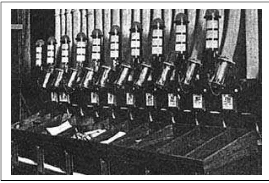
The first practical implementation of PCP or PTS technology was between the Central offices of the Electric and International Telegraph Company on Telegraph Street in London, and their offices at the Stock Exchange in the City of London, in 1853. Figure 2.1 is an example of A pneumatic tube table, Central Telegraph Office, London, during the 1930s (MacGregor, J, 1930s).The system conveyed messages which had been transcribed from the telegraph. Mr. Josiah Latimer Clark installed 675ft of 1 1/2 inch diameter tube, with messages conveyed in bags by pressure differentials generated by a single 6 (hp) engine.
In 1858 the Electric and International Telegraph Company built another tube 3,120 ft long with a diameter of 2 1/4 inches, to an unknown location within London. Other tubes followed. By 1860 the Electric and International Telegraph Company systems had linked their central office in Lothbury with stations at the stock exchange, and at Cornhill (Anon, 1860). Systems were also installed outside of London, for example, that installed by Mr C. A. Varley in July 1864 in Liverpool (Anon, 1864). This linked the Electric Telegraph Company office in Castle Street and an office in Walter Street, a distance of 300 yards. The system was not only the first outside of London, but also the first recorded installation of a system in which messages could be sent in both directions, using the same pipe: capsules were propelled by compressed air in one direction, and a vacuum in the other. This technique became common for use on systems with relatively low throughput of capsules.
It was not until the development of the 'double valve' by Willmott, J. W. in 1870, that significant network of telegram conveying tubes developed. The double sluice valve overcame the problems associated with more than one message in a tube at one time. By 1874 an extensive system of tubes was in place, linking the Central Telegram Office at Martin's le Grand in London, with London's district post offices, distributing around 4.5 million messages annually. By 1886 London had 94 telegram tubes totaling 34 1/2 miles, powered by four 50 hp engines.
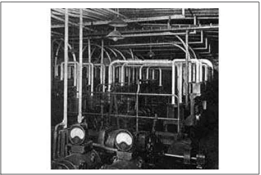
system also is automatically system. Figure 2.2 is an example of the automatic switch room for the London Street Tube System (MacGregor, J, 1930s).
Figure 2.2: The automatic switch room for the London Street Tube System (MacGregor, J, 1930s)
carriers were allowed, although they had to be dispatched at regular intervals. The carrier was then drawn along the tube at an average speed of 30 feet per second, or 20 mph. Street tubes, which varied in length from a few hundred feet to over three miles, required pressures of up to 12 lbs per sq inch above atmosphere in order to achieve these speeds. This pressure is created by supplying compressed air at one end of the tube, and leaving the other open to the atmosphere; or alternatively leaving one end open to the atmosphere and exhausting the air at the other by means of a suction pump which maintains partial vacuum in the tube. Initially air differentials were created by steam driven beam engines. By the 1930s, two electrically driven compressors operate all street tubes in London. (http//www.capsu.org // Pneumatic Capsule Pipelines // History)
2.2 Profitability
2.2.1 Why PTS?
Because PTS can solves internal transport problems with a speed of 20-25 ft /sec. That can save time, energy and allows your staff to concentrate on more important matters instead of running errands.
The profitability of PTS could be calculated as follows:
R x T / 60 (http//www.aerocom-usa.com/) where:
R = Route (how often)
T = Time spent per route in minutes