DOI: 10.12928/TELKOMNIKA.v14i3.3998 856
Design and Fabrication of Compact MEMS
Electromagnetic Micro-Actuator with Planar Micro-Coil
Based on PCB
Roer Eka Pawinanto1, Jumril Yunas*2, Burhanuddin Yeop Majlis3, Azrul Azlan Hamzah4 Institute of Microengineering and Nanoelectronics (IMEN), Universiti Kebangsaan Malaysia (UKM),
43600 UKM Bangi, Selangor, Malaysia
*Corresponding author, e-mail: [email protected], [email protected], [email protected], [email protected]
Abstract
This paper reports a compact design of electromagnetically driven MEMS micro-actuator utilizing planar electromagnetic coil on PCB (Printed Circuit Board). The micro-actuator device consists of an NdFeB permanent magnet, thin silicon membrane and planar micro-coil which fabricated using simple standard MEMS techniques with additional bonding step. Two planar coils designs including planar parallel and spiral coil structure with various coil geometry are chosen for the study. Analysis of the device involves the investigation of electromagnetic and mechanical properties using finite element analysis (FEA), the measurement of the membrane deflection and functionality test. The measurement results show that the thin silicon membrane is able to deform as much as 12.87 µm using planar spiral micro-coil. Reasonable match between simulation and measurement of about 82.5% has been revealed. The dynamic response test on actuator driven by parallel planar coil shows that silicon membrane effectively deformed in 40 s for an input electrical power of only 150 mW. It is also concluded that planar parallel coil is considered for the simple structure and easy fabrication of the actuator system. This study will provide important parameters for the development of compact and simple electromagnetic micro-actuator system for fluidic injection system in lab-on-chip.
Keywords: MEMS, electromagnetic micro-actuator, printed circuit board (PCB), silicon membrane, planar micro-coil
Copyright © 2016 Universitas Ahmad Dahlan. All rights reserved.
1. Introduction
MEMS micro-actuators have recently attracted research interest in the fields of biomedical and chemical analysis due to their simple and compact structures [1], low and controllable power consumption [2] and fast response time [3]. Especially silicon based micro-actuator driven by electromagnetic field is the key component of microfluidic pumping system that finds its important role for biological sample injection in lab-on-chip system [4] and drug delivery system applications [5, 6] where accurately delivery of small quantity of liquid is required [7].
Electromagnetic actuator is driven by magnetic forces generated by current carrying conductive spiral coil, such as solenoid, toroid and planar coil. Among all the coil types, planar coils have been found as the simplest and most suitable structure for used in multilayer structure. Planar coil reduces the device volume as much as 10 times as compared to solenoid model [8].
Several techniques to fabricate planar micro-coils have been reported before. Some of standard microelectronic mechanical system (MEMS) fabrication technique such as metal deposition using vacuum evaporator or DC-sputtering [9], deposition of conductive polymer implementing SU8 micromolding [10], metal electroplating and electroless plating on silicon substrate [11], are preferred to fabricate the coil structure because of the familiarity of the process adopted from IC technology.
al., [9] and Woytasik, et al., [11] require expensive metal target and equipment. On the other hand, it has been reported previously that microfluidic chip is packaged on printed circuit board (PCB) platform to reduce cost and enable effective integration between the lab-on-chip system with other electronics parts [12-14].
Therefore, we report in this paper the development of silicon based micro-actuator with planar micro-coil structure developed on PCB. Utilization of existing copper on the PCB layer used to fabricate micro-coil structure can reduce fabrication costs and ease of fabrication. The study is focused on exploring the PCB based coil design and geometry that is able to generate uniform and optimum magnetic flux density to produce optimum membrane displacement. The fabrication technology of the actuator system and the functionality test of the fabricated structure are also presented.
2. Basic Principle of Electromagnetic Micro-actuator
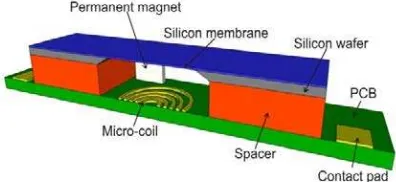
The basic structure of electromagnetic micro-actuator consists of three main parts namely an electromagnetic micro-coil, a permanent magnet and a mechanical membrane, as schematically shown in Figure 1. Basically, the working principle of electromagnetic actuator is depending on magnetic force acting on a flexible membrane that is produced by the interaction between magnetic fields generated by current carrying micro-coil with permanent magnet.
Figure 1. Schematic Structure of the MEMS EM Actuator
The analytical equation for the magnetic field generated by a circular coil is given by the Biot-Savart law. For a single turn circular coil, with radius r, the magnetic field at a distance z along its central axis, is given by Equation (1):
�(�) = ��2 2(�2+�2)32
(1)
Where I is the current, r is the mean radius of the turn and z is the distance along the z-axis. To obtain the magnetic field of a coil with N turns, the total generated magnetic field is the sum of all magnetic fields generated by each turn. Meanwhile, the magnetic force produced for the system in Figure 1 is described in Equation (2):
Fz= BrAg∫ ∂Hz ∂z dz z+hg
z (2)
Where Fz is the magnetic force, Br is the remanence of the magnetic material, Ag and hg are the surface area and thickness of the magnet, respectively. The correlation between magnetic force applied on the membrane and the resulting membrane displacement dz can be derived from Equation (3):
��=�����
2
� (3)
�= �ℎ�2
12(1−�2) (4)
Where E is the Young’s modulus of the material, v is Poisson’s ratio and hm is the thickness of the membrane.
3. Design of Electromagnetic Micro-actuator 3.1. Permanent Magnet
Bulk permanent magnet used for this proposed device is made of NdFeB material with diameter and thickness of 3 mm and 1.5 mm, respectively. The magnet is attached to the silicon membrane using epoxy material. The magnetic force is dependent on the magnetic field strength, magnetic material volume and the distance between the magnet and the electromagnetic coil along the z-axis.
3.2. Mechanical Membrane
In this study, silicon material is used as the membrane due to the best material strength and simplest fabrication process compared to other materials such as polyimide and polydimethylsiloxane (PDMS). Furthermore, silicon material has high thermal conductivity that prevents the release of permanent magnet attached on the membrane due to the heat concentration. However, silicon material is more rigid than polyimide or PDMS, due to its high modulus elasticity of approximately 169 GPa [15].
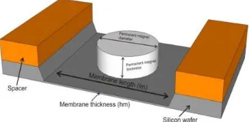
Figure 2. The Schematic of Membrane Geometry with Attached Permanent Magnet
(a) (b)
Figure 3. Types Of Studied Micro Coil Structure: (a) Planar Parallel Circular Micro-Coil. (b) Planar Spiral micro-coil
Table 1. The Geometrycal Parameter of Planar Micro-Coil used in the Study
Sample type Coil 1 Coil 2 Coil 3 Coil 4
Width (µm) 100 200 150 100
Space (µm) 150 100 100 100
Thickness (µm) 30 30 30 30
Inner diameter (mm) 2.5 2.5 2.5 2.5
The geometry of the membrane and silicon chamber used in this work is shown in Figure 2. In terms of space requirements, the membrane area should be large enough to accommodate the surface area of the magnet. Therefore In this work, the membrane surface area was set to 6x6 mm2 with total chamber volume including spacer of 6x6x2 mm3 to provide enough space for a free movement, meanwhile the glass material was used for the spacer.
3.3. Planar micro-coil
Two types of planar micro-coil are investigated in this study including planar parallel circular micro-coil and planar spiral micro-coil, as shown in Figure 3. The geometry of the planar micro-coil is varied as listed in Table 1. The micro-coil parameters that are kept constant are inner diameter, thickness and the number of coil turns of 2.5 mm, 30 µm and 5, respectively.
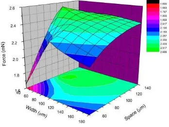
Electromagnetic force generated is strongly affected by the dimension of planar micro coil. Therefore, planar micro coil simulation with various dimensions was necessary. In this simulation, constant electrical current of 500 mA was applied. The simulation result shown in Figure 4 reveals that the optimum magnetic force was generated at the coil width and space with the range between 80 80 µm to 100 µm. This optimum generated electromagnetic force was uniformly distributed on the surface of planar micro coil as show in Figure 5.
Figure 4. The Simulation Result of Electromagnetic Force
Figure 5. Distribution of Magnetic Flux
From Equation (1), it can be estimated that the smaller the area radius of the planar micro-coil, the higher magnetic field can be generated. Therefore, the design should consider the variation between space and width of the coil in order to obtained optimal geometry.
4. Actuator Fabrication
The important components of electromagnetic micro-actuator are the membrane, chamber and the electromagnetic coil. In this work, the micro-actuator membrane and the chamber is made of silicon material that is fabricated using standard silicon process. Here, the silicon membrane was fabricated by anisotropic etch of 375 µm thick silicon wafer <100> using KOH solution at 75 oC with controllable slow etch rate of 78 nm/min. Another etchant solution such as HNA is able to create the chamber however large under etch and unpredicted etch rate was observed [16].
Anistropic etching technique is used due to the cost effectiveness and simplicity of the process compared to the deep reactive ion etching (DRIE) or others istropic etching. The advantage of microcoil fabricated on the PCB is simpler than fabricated microcoil on silicon substrate, because it does not need metal deposition process. Nevertheless, the space geometry of fabricated microcoil bellow than 100 µm is hard to achieve due to the fabrication limitation such as low photolithography mask resolution.
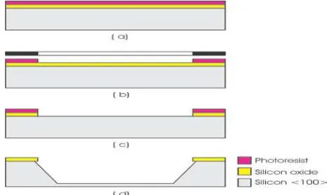
1:2 AZ 400 K dilution with DI water (b), Opening the oxide layer using 10 % BOE for 100 minutes (c) and follow with photoresist removal using acetone. The silicon substrate was then anisotropically etched using KOH etchant to produces silicon chamber and membrane (d).
Figure 5. Membrane Fabrication Step, (a) Photoresist Coating. (b) Membrane Patterning, (c) Oxide Etching, (d) Silicon Etching
(a) (b)
Figure 6. The result of fabricated silicon membrane and chamber, (a) SEM image of silicon trench for the actuator chamber after anisotropic etching, (b)
SEM image of fabricated membrane having the thickness of 20 µm
Figure 7. Fabrication Process of Planar Coil, (a) Photoresist Coating. (b) Photoresist Patterning, (c) Copper Etching and Photoresist Removing
successfully fabricated after etching the silicon substrate. A side slope of about 54o with smooth and flat membrane surface were also observed.
Figure 7 shows the fabrication step of planar electromagnetic micro-coil. The planar coil is made of 30 µm copper material electroplated on PCB substrate. The process step of the micro-coil fabrication is simple requiring only 1 lithography process.
Initially, photoresist AZ 4620 was spin coated onto PCB surface to form the coil pattern (a). UV light was then exposed for 80 seconds when the exposure energy is 250 mJ/cm2 and developed in AZ 400k 1:2 for 50 seconds (b). Finally, the micro-coil structure was produced after copper etching process by 70 % FeCl3 for 1 hour 20 minutes with an etching rate of about 0.375 µm/min to etch 30 µm copper (c).
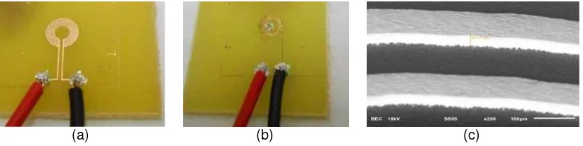
Figure 8 shows the result of the coil fabrication for the both coil types, namely (a) planar parallel circular micro-coil and (b) planar spiral micro-coil. (c) SEM of micro coil thickness.
(a) (b) (c)
Figure 8. The Fabrication Result of Micro-Coil. (a) Planar Parallel Circular Micro-Coil. (b) Planar Spiral Micro-Coil. (c) SEM Image of Micro Coil Thickness
The next part of the micro-actuator fabrication is the attachment of permanent magnet on to the silicon membrane using epoxy. The permanent magnet is cylinder type with diameter and thickness of 3 mm and 1.5 mm, respectively.
The electromagnetic micro-coil, silicon chamber and membrane including permanent magnet are then finally integrated by bonding all micro-actuator parts using epoxy completing the structure as shown in Figure 9.
Figure 9. The Micro-Actuator after Integration of All Parts
5. Results and Discussions 5.1. Measurement Results
Figure 10 illustrates the setup for the measurement of actuator performances. The measurement system consists of Keyence LC-2400 displacement meter with the laser probe, measurement stage and power supply.
relaxation time characteristic of silicon membrane to adjust the plastic deformation capability of the material for bending.
It is also observed that after 40 sec, the membrane displacement decreases slightly which is due to the heat effect of the coils reducing the generation of electromagnetic field and the efficiency of the energy transfer.
(a) (b)
Figure 10. (a) The Schematic of the Set Up for the Measurement of Membrane Displacement, (B) Photography of the Measurement System
(a) (b)
(c) (d)
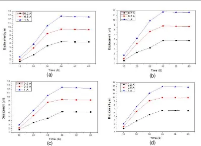
Figure 11. Relationship between deformation time and measured micro-actuator displacement of planar parallel circular micro coil at various applied input current. (a) coil 1 with w=100 µm, s=150 µm. (b) coil 2 with w=200 µm, s=100 µm. (c) coil 3 with w= 150
(a) (b)
(c) (d)
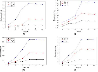
Figure 12. Relationship between Deformation Time and Measured Micro-Actuator Displacement of Planar Spiral Micro-Coil at Various Applied Input Current. (a) coil 1 with
w=100 µm, s=150 µm. (b) coil 2 with w=200 µm, s=100 µm, (c) coil 3 with w= 150 µm, s=100 µm, (d) coil 4 with w= 100 µm, s= 100 µm
(a) (b)
Figure 13. The Geometric Layout Design Model, (a) 2D Axisymmetric, (b) 3D Model
In Figure 12d it is shown that micro-actuator with planar spiral micro-coil 4 (width= 100 µm and space= 100 µm) produces a maximum membrane displacement of approximately 10.1 µm for an input current of 500 mA, which is the highest deflection among all types. This is due to the better current distribution along the micro-coil and more efficient magnetic field generation at the coil center.
On the other hand the micro-actuator with planar parallel coil achieved maximum membrane displacement of approximately 2.75 µm, which is almost 3 times lower that of planar spiral coil type (see Figure 11d).
It is also shown in Figure 12 that the fabricated actuator with planar spiral micro-coil types can achieve displacement height within the range of 4 to 13 µm for input current between 200 mA to 1A.
model used for displacement simulation as show in Figure 13 and the solid mechanics module was also applied. The micro-coil geometry and others micro actuator parameter were varied as shown Table 2. Furtehrmore, air medium parameter is used for the boundary condition.
Table 2. Micro Actuator Parameters
Sample type Micro-coil 1 Micro-coil 2 Micro-coil 3 Micro-coil 4
Micro coil
Material Copper Copper Copper Copper
Membrane
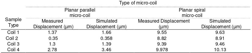
The measurement results are summarized in Table 3. It is shown that the simulated membrane deflection is higher than that of measurement for all coil configurations which is due to the ideal simulation condition. On the other hand, there are several lost in measurement process such as resistances of the wires, Gauss meter and power supply that affect to the power efficiency delivered to the coils. However it can be seen that reasonable match between simulation and measurement of about maximum 82.5 % was obtained.
Table 3. Comparison between Measurement and Simulation Results of Membrane Deflection for 0.5 A Input Current
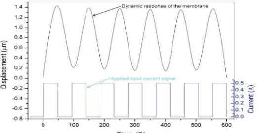
Figure 14 shows the dynamic response of the micro-actuator for the functionality test purpose. An applied current of 500 mA at planar parallel circular micro-coil (1) was intermittently turned ON and OFF within a period of about 50 seconds. For the ON state condition, it is shown that the membrane is able to deform effectively within 40 seconds with the maximum deflection of 1.4 µm for only 150 mW electrical power consumption (see also Figure 10a). While at OFF state condition, it can be seen that the membrane cannot return to its starting position, which is due to the lack on membrane elasticity after deformation and loss of electromagnetic force hence requiring more time to release its surface stress
Figure 14. Dynamic Response of Fabricated Micro-Actuator for Intermittent Electricity Input of 0.5 A at Planar Parallel Circular Micro-Coil 1
4. Conclusion
The silicon based electromagnetic micro-actuator using planar micro-coil on PCB has been successfully fabricated and tested. Two types of planar micro-coil including variation of coil geometry were chosen for the investigation. The results showed that a reliable electromagnetic micro-actuator can be designed and fabricated using simple and cheap MEMS process. It was also shown that planar micro-coils are able to produce an optimum Silicon membrane displacement of approximately 12.87 µm. Reasonable match between simulation and measurement of about 82.5% has been also revealed. It was also concluded that planar parallel circular coil is able to deform the silicon membrane effectively within 40 seconds with the maximum deflection of 2.75 µm for only 200 mW electrical power consumption. This actuator type is considered for the simple structure with easy fabrication that will benefit the development of compact micropump integrated in Lab on Chip.Provide a statement that what is expected, as stated in the "Introduction" chapter can ultimately result in "Results and Discussion" chapter, so there is compatibility. Moreover, it can also be added the prospect of the development of research results and application prospects of further studies into the next (based on result and discussion).
Acknowledgements
The authors acknowledge the financial support from Universiti Kebangsaan Malaysia for supporting this project under ERGS grant no. ERGS/1/2013/TK02/UKM/02/3.
References
[1] X Lv, W Wei, X Mao, Y Chen, J Yang, F Yang. A novel MEMS electromagnetic actuator with large displacement. Sensors Actuator A: Physical. 2015; 221: 22-28.
[2] J Sutanto, PJ Hesketh, YH Berthelot. Static and dynamic responses of an electromagnetic bistable– bidirectional microactuator on a single silicon substrate. Sensors and Actuators A: Physical. 2006; 132: 701-713.
[3] HL Yin, YC Huang, W Fang, J Hsieh. A novel electromagnetic elastomer membrane actuator with a semi-embedded coil. Sensors and Actuators A: Physical. 2007;139: 194–202.
[4] J Ni, B Wang, S Chang, Q Lin. An integrated planar magnetic micropump. Microelectronic engineering. 2014; 117: 35-40.
[5] J Johari, J Yunas, AA Hamzah, BY Majlis. Piezoelectric micropump with nanoliter per minute flow for drug delivery systems. Sains Malaysiana. 2011; 40(3): 275-281.
[6] A Nisar, N Afzulpurkar, B Mahaisavariya, A Tuantranont. MEMS-based micropumps in drug delivery and biomedical applications. Sensors and Actuators B. 2008; 130: 917–942.
[7] J Getpreecharsawas, I Puchades, B Hournbuckle, L Fuller, R Pearson, S Lyshevski. An Electromagnetic MEMS Actuator for Micropumps, Proceedings of the 2nd International Conference on Perspective Technologies and Methods in MEMS Design, 2006, MEMSTECH. 2006: 11-14. [8] J Yunas, BY Majlis. Comparative study of stack interwinding micro-transformers on silicon monolithic.
[9] M Amato, F Dalena, C Coviello, M De Vittorio, S Petroni. Modeling, fabrication and characterization of micro-coils as magnetic inductors for wireless power transfer. Microelectronic Engineering. 2013; 111: 143-148.
[10] T Kohlmeier, V Seidemann, S Buettgenbach, HH Gatzen. An investigation on technologies to fabricate microcoils for miniaturized actuator systems. Microsystem Technologies. 2004;10(3): 175– 181.
[11] M Woytasik, J Moulin, E Martincic, AL Coutrot, E Dufour-Gergam. Copper planar microcoils applied to magnetic actuation. Microsyst Technologies. 2008; 14(7): 951-956.
[12] C Aracil, F Perdigones, A Luque, JM Quero. Microfluidic impulsion system manufactured by PCB-MEMS for Lab on a Chip. IEEE conference of Electron Devices (CDE). 2013: 131-134.
[13] J Li, Y Wang, E Donga, H Chen. USB-driven microfluidic chips on printed circuit boards. Lab Chip. 2014; 14: 860-864.
[14] S Gassmann, L Pagel. Magnetic actuated pressure relief valve. Sensors and Actuators A: Physical
2013; 194: 106–111.
[15] N William, Sharpe Jr, B Yuan, R Vaidyanathan, R Edwards. Measurements of Young’s Modulus, Poisson’s Ratio, and Tensile Strength of Polysilicon. Proceedings of the Tenth IEEE International Workshop on Microelectromechanical Systems. Nagoya, Japan. 1997: 424-429.
[16] AA Hamzah, NA Aziz, BY Majlis, J Yunas, CF Dee, B Bais. Optimization of HNA etching parameters to produce high aspect ratio solid silicon microneedles. J. Micromech. Microeng. 2012; 22(095017): 10.