6
International Journal of Energy and Power Engineering Research 1 (2013) 6-9SIMULATION AND EXPERIMENTAL WORK OF KINEMATIC PROBLEMS FOR
KUKA KR 5 SIXX R650 ARTICULATED ROBOT
Marizan Sulaiman1, M.I.K. Syaffiq1, Azmi Said1, H.N.M. Shah1 and M.N. Fakhzan2 1
Faculty of Electrical Engineering,
Universiti Teknikal Malaysia Melaka, Hang Tuah Jaya, 76100 Durian Tunggal, Melaka, Malaysia 2
School of Mechatronic Engineering,
Rumah Universiti, Universiti Malaysia Perlis, Kampus Kubang Gajah,02600 Arau, Perlis Email: [email protected] movement in order to study three types of path motion used in the robotic arm. The three path motions are PTP (point-to-point), linear and circular. The motions are analyzed systemically using forward kinematics and inverse kinematics. The objective of forward kinematic analysis is to determine the cumulative effect of the entire set of joint variables. A simulation oriented analysis is obtained and comparison between simulation and experimental result is done. The result for both simulation and experimental works show close connection for the task. This robot is suitable to be applied to the teaching and training environment.
Keywords: Kinematics, Manipulator, Trajectory, Robotic
Arm
1. INTRODUCTION
Nowadays, robotic arms are used in various applications and environment. Each of them has their own complexity and uniqueness in order to fulfill the task given. However, many advance technologies are severely restricted in commercial system due to limitation of the controller rather than the manipulator arms (Kay, 2005). In order to overcome this limitation there were several systems been develop for example vision based system (Haniff et al. 2011). A robotic manipulator is designed to perform a task in the 3-D space. The tool or end-effector is to follow a planned trajectory to manipulate objects or carry out the task in the workspace. This requires control of position of each link and joint of the manipulator to control both the position and orientation of the tool (Lombai et al. 2008).
In order to understand how to control the position of each link and joint of the manipulator, it is important to analyze the kinematic solution of the robot. There are two kinematic topics discuss in this paper that is forward and inverse kinematic. Forward kinematic is about finding position of any coordinates by referring to the given length of each link and angle of each joint while inverse kinematic is about finding angles of each joint needed to obtain the position based on given length of each link and the position (Xu D. et al. 2005).
In this paper the focus will be on the forward kinematics and inverse kinematics problem of a KUKA KR 5 SIXX R650 robotic arm. KUKA Robotics is a well-known Germany manufacturer of industrial robots for various industrial processes. The robotic arm comes with a teaching pendant that has a display and an integrated mouse where manipulator is move or positions are create, edit and save. The latest teaching pendant uses the Windows XP operating system. The KR 5 SIXX R650 is a 6-axes robotic arm weighting 28kg with the payload up to 5kg (KUKA). This paper will focus specifically on the use of this type of robotic arm in a simple two point’s movement process.
2. METHODOLOGY
2.1Kinematic Theory and Analysis
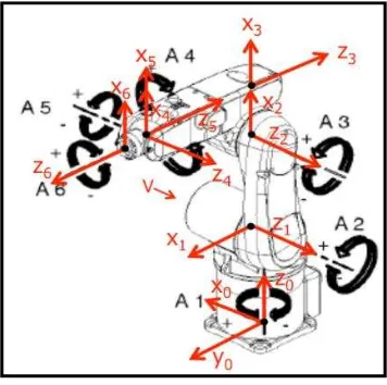
In order to analyze the kinematic of arm robot, it is important to identify the coordinate frames. The zi axis for
all joints will follow the direction of rotation and the right-handed rule is use to identify the rotation (Diaz et al. 2010). Referring to Figure 1, at joint 1, z0 is representing the first
7
Figure 1 Joints of KUKA KR 5 SIXX R650
Table 1 Denavit-Hartenberg Parameters of All Links and Joints
Calculating the position and orientation of the end-effector in terms of the joint variables is called as forward kinematics. In order to have forward kinematics for a robot mechanism in a systematic manner, one should use a suitable kinematics model. Denavit-Hartenberg method that uses four parameters is the most common method for describing the robot kinematics (Gan et al. 2010). This method is used for systematically establishing a coordinate system to each link of an articulated robot. The standard 4x4 homogeneous coordinate transformation matrix can be use to represent the transformation between adjacent coordinate frames when the coordinate frames are assigned (Verma et al. 2010). Frame [i-1] and frame should be consider [i] in order to find the transformation matrix relating two frames attached to the adjacent links. The transformations of frame [i-1] to frame [i] consists of four basic transformations.
1. A rotation about zi-1 axis by an angle θi;
2. Translations along zi-1 axis by distance di; 3. Translation by distance ai along xi axis and 4. Rotation by an angle αi about xi axis
The transformations between each two successive joints can be written by simply substituting the parameters from the parameters table into the H matrix.
8
Fiq. 2 Linear movementFig. 3 PTP movement
Fig. 4 Circular movement
3. RESULTS AND DISCUSSION 3.1 Simulation Results
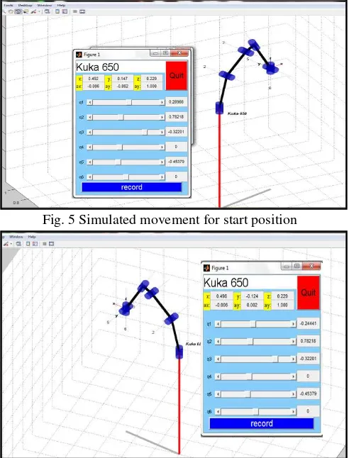
The data from the changing angle on the joint will be simulated using Matlab RVC toolbox. This is to ensure every joint will produce accurate movement and the required end point. Fig. 5 describes the output of the simulation for start point of the robotic arm located at coordinate [0.492 0.147 0.229]. While Fig. 6 shows the endpoint for the robotic arm movement located at coordinate [0.498 -0.124 0.229]. All measurements are in meter.
3.2 Experimental Results
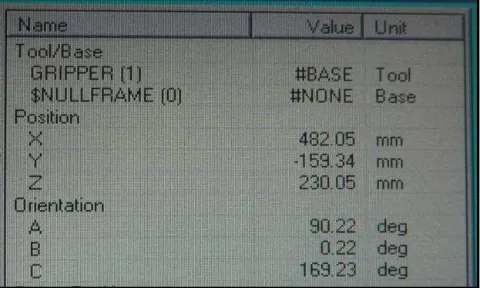
Fig. 7 describes the result of the experimental for start point of the robotic arm located at coordinate [482.35 134.38 230.02]. While Fig. 8 shows the experimental axis angle for start position. Fig. 9 describe the end position for the robotic arm movement located at coordinate [482.05 -159.34 230.05]. All measurements are in mm. Based on the results obtain, there are slightly different value for robot coordinates between simulation and experimental results. However this will not be an issue because both works are
conducted separately. So it is common to have slight different. All three motion path (PTP, linear and circular) shows the same value for start point and endpoint coordinates. In experimental works, the different for these three motion path can be seen through the robotic arm movement. However in simulation works the robotic arm model in Matlab unable to simulate any three path motions due to software constraint.
Fig. 5 Simulated movement for start position
Fig. 6 Simulated movement for end position
Fig. 7 Experimental robot coordinates for start position S
S
S
E
E
M
9
Fig. 8 Experimental axis angle for start positionFig. 9 Experimental robot coordinates for end position
4. CONCLUSION
The simulation results have shown that forward and inverse kinematics is successfully developed using KUKA KR5 SIXX R650 robotic arm model in MATLAB RVC toolbox. A general D-H representation of forward and inverse kinematic is obtained. Moreover, the experimental results also have verified the simulation work. Future work will focus on the optimization of energy utilization.
ACKNOWLEDGEMENT
The authors wish to thanks Universiti Teknikal Malaysia Melaka for its support through the grant MTUN/2012/UTeM-FKE/3 M00011.
REFERENCES
Diaz J., Dutra M. and Fernando A. 2010. Kinematical and Dynamical Models of KR 6 KUKA Robot. 601-620.
Gan Q., Eric M. R. 2010. Forward and Inverse Kinematics Models for a 5-DOF Pioneer 2 Robot Arm. 1-33. Haniff, S. Marizan, Shah H. N. M., Teck L. W. 2011.
Shape-Based Matching: Defect Inspection of Glue Process in Vision System. 53-57.
Herman M., Azmi M., Marizan S., Horng C. H. 2006. Vision Guided Manipulator for Optimal Dynamic Performance. Proceedings of the IEEE Student Conference on Research and Development, Selangor, Malaysia: 67-77.
Ibrahim M. Y., Cook C. D., Tieu A. K. Effect of a Robot's Geometrical Parameters on Its Optimal Dynamic Performance: 820-825.
Kay J. 2005. Introduction to Homogeneous Transformation and Robot Kinematics. 1-25.
KUKA Robotic Corporation [Online]: http://www.kuka-robotic.com
Lombai F., Gabor S. 2008. Trajectory Tracking Control of a 6-Degree-Of-Freedom Robot Arm Using Nonlinear Optimization: 655-660.
Verma A., Gor M. 2010. Forward Kinematics Analysis of 6-DOF Arc Welding Robot. International Journal of Engineering Science and Technology 2: 4682-4686.