PROJECT COMPLETION REPORT
FOR
SHORT TERM RESEARCH GRANT
OPTIMIZATION OF CROSS-FLOW TURBINE
FOR
PICO-HYDRO SYSTEM
Principal Researcher : Associate Professor Juhari Bin Ab. Razak Co-Researcher : 1. Masjuri Bin Musa @ Othman (FKM)
2. Professor Dr. Md. Razali Bin Ayub (FKM) 3. Safarudin Herawan Gazali (FKM)
4. Mohd. Afzanizam Bin Roosli (FKM)
Project Code No. : PJP/2010/FKM(17B)/S00731 Report Submission Date : 21 June 2013
ii
ACKNOWLEDGMENT
First of all, the author would like to express thankfulness to Allah the all mighty because the team members have managed to finish this Short Term Project. This project will not be succeeded without the involvement from the team members who were really committed in completing their tasks.
iii
ABSTRACT
iv
ABSTRAK
v
TABLE OF CONTENTS
CHAPTER CONTENT PAGE
ACKNOWLEDGEMENT ii
ABSTRACT iii
ABSTRAK iv
TABLE OF CONTENTS v
LIST OF TABLE xi
LIST OF FIGURE xii
vi
CHAPTER CONTENT PAGE
CHAPTER 1 INTRODUCTION 1
1.1 Pico Hydro Scheme 1
1.2 Problem Statement 3
1.3 Objective 3
1.4 Scope 3
CHAPTER 2 LITERATURE REVIEW 4
2.1 Hydro Power 4
2.1.1 History of Hydropower 4
2.1.2 Classification of Hydropower 5
2.2 Status and Applications 6
2.3 Pico Hydro Power System 7
2.4 Types of Turbine 10
2.4.1 Impulse Turbine 10
2.4.2 Reaction Turbine 13
2.5 Selection of Turbine 15
2.5.1 Head and Flow Rate 15
vii
CHAPTER CONTENT PAGE
CHAPTER 2 2.5.3 Capacity Factor 20
2.5.4 Energy Output 20
2.5.5 Efficiency 20
2.5.6 Specific Speed 21
2.5.7 Diameter and Length 22
2.6 Cross-Flow Turbine 22
2.6.1 Hydraulic Parameters and Operation
Principles 22
2.6.2 Parameters Affecting Cross-Flow
Turbine Performance 24
2.7 Velocity Distributions on Runner Blades 27
2.8 Pressure Distributions on Runner Blades 30
CHAPTER 3 METHODOLOGY 32
3.1 Introduction 32
3.2 Project’s Flow Chart 33
3.3 Material Selection 34
3.3.1 Stainless Steel 34
3.3.2 Mild Steel 35
viii
CHAPTER CONTENT PAGE
CHAPTER 3 3.4 Design Stage 35
3.4.1 Design Principles 36
3.4.2 Software Application 36
3.5 Conceptual Drawing 37
3.6 Main Component 38
3.6.1 Turbine/Rotor Section 38
3.6.2 Blade 39
3.6.3 Side Cover Plate 39
3.6.4 Housing/Main Structure 40
3.6.5 Gear System 41
3.7 Fabrication Process 41
3.7.1 List of Fabrication Parts 42
3.7.2 List of Standard Parts 42
3.7.3 Welding Process 42
3.8 Coating 44
ix
CHAPTER CONTENT PAGE
CHAPTER 4 RESULTS 47
4.1 Fabrication of Cross-Flow Turbine 47
4.2 Finite Element Analysis 51
4.2.1 Main Structure 51
4.2.2 Runner Blade 53
4.3 CFD Analysis 55
4.4 Power Output Calculation 58
CHAPTER 5 DISCUSSION 60
5.1 Introduction 60
5.2 Discussion on the Analysis Data 60
5.3 Discussion of CFD Analysis 61
5.4 Bill of Materials (B.O.M) 62
5.4.1 Fabrication Parts 62
5.4.2 Standard Parts 62
x
CHAPTER CONTENT PAGE
CHAPTER 6 CONCLUSION AND RECOMMENDATION 64
xi
LIST OF TABLE
NO. TITLE PAGES
2.1 Classification of Hydropower (Adewoyo, 2009) 5
2.2 Type of Turbine (Zainuddin et al. 2009) 10
2.3 Blade Angles at Runner Inlet and Outlet (Choi, 2008b) 29
2.4 Number of Runner Blades (Choi, 2008b) 29
3.1 Fabrication Parts 42
3.2 Standard Parts 42
4.1 The Power Output produced for each values of Water
Flow Rates 59
5.1 Maximum Velocity of the Streamline vs
Flow Rate of Water 61
5.2 Fabrication Parts of BOM for Cross-flow Turbine 62
5.3 Standard Parts of BOM for Cross-Flow Turbine 62
xii
LIST OF FIGURE
NO. TITLE PAGES
2.1 Component of Pico Hydro System
(Maher and Smith, 2001) 8
2.2 Pelton Turbine (Adewoyo, 2009) 11
2.3 Turgo Turbine (Adewoyo, 2009) 12
2.4 Crossflow Turbine (Adewoyo, 2009) 13
2.5 Propeller Turbine (Adewoyo, 2009) 14
2.6 Kaplan Turbine (Adewoyo, 2009) 14
2.7 Spiral Cased Francis Turbine (Adewoyo, 2009) 15
2.8 Head-Flow Ranges of Small Hydro Turbines
(Paish, 2002) 16
2.9 Efficiency of Small Hydro Turbines
(Kaldellis et al. 2005) 21
2.10 Schematic Diagram of Cross-Flow Turbine
(Source: Wakati, 2010) 23
2.11 Cross-flow turbine angle of attack investigation 25
2.12 Summary of investigations on number of blades for
Cross-flow turbine 27
xiii
NO. TITLE PAGES
2.15 Pressure Contours within the flow field 30
3.1 Process Flow Chart for the whole project 33
3.2 Stainless Steel Plate 34
3.3 Mild Steel Plate 35
3.4 Conceptual Drawing of complete Cross-Flow Turbine 37
3.5 Turbine 38
3.14 The Schematic Diagram of the complete system of
the test-rig 45
3.15 Manufactured test-rig 46
4.1 Blade 47
4.2 Side Cover of the Cross-flow Turbine 48
4.3 Rotor section of the Cross-flow Turbine 48
4.4 Housing of Main Structure 49
4.5 Guide Vane 49
4.6 Alternator Holder 50
4.7 Cross-Flow Turbine 50
4.8 Stress Analysis (Casing) 51
4.9 Displacement Analysis (Casing) 52
xiv
NO. TITLE PAGES
4.11 Displacement Analysis (Blade) 54
4.12 Flow Rate 10 L/s 55
4.13 Flow Rate 20 L/s 56
4.14 Flow Rate 30 L/s 56
4.15 Flow Rate 40 L/s 57
4.16 Flow Rate 50 L/s 58
5.1 A Graph Maximum Velocity of the Streamline vs
xv
LIST OF SYMBOL
m = Mass of water (kg).
g = Acceleration due to gravity (9.81 m/s2),
H = Effective pressure head of water across the turbine (m).
c = Jet velocity of water at the intake of the turbine blade (m/s).
P = Mechanical power produced at the turbine shaft (Watts),
η = Hydraulic efficiency of the turbine, ρ is the density of water
(1000 kg/m3),
1
CHAPTER 1
INTRODUCTION
1.1 PICO HYDRO SCHEME
Pico hydro is a type of hydropower which capable to produce electrical output up to 5 kilowatts. Pico-hydro systems benefit in terms of cost, its simplicity from different approaches in the design, planning and installation compared to those which are applied to larger hydropower scheme. The pico-hydro scheme is more preferred due to its effectiveness in producing power output, cost-effective, clean, user friendly and do not involve with huge construction works. Recent innovations in Pico-hydro technology have made it an economic source of power even in some of the poorest and most inaccessible places around the world gained the benefits from this green technology application. It is also a versatile power source. Alternating Current (AC) electricity can be produced enabling standard electrical appliances to be used and this electricity can be distributed to the whole village.
Common examples of devices which can be powered by Pico-hydro are light bulbs, radios, televisions, refrigerators and food processors. On the other hand, mechanical power can be utilised with some designs. This is useful for direct drive of machinery such as workshop tools, grain mills and other agro-processing equipment.
2
a) Often, small communities are without electricity even in countries with extensive grid electrification. Despite the high demand for electricity, grid connection of small communities remains unattractive to utilities due to the relatively low power consumption.
b) Only small water flows are required for Pico-hydro so there are numerous suitable sites. A small stream or spring often provides enough water.
c) Pico hydro equipment is small and compact. The component parts can be easily transported into remote and inaccessible regions.
d) Local manufacture is possible. The design principles and fabrication processes can be easily learned. This keeps some equipment costs in proportion with local wages.
e) The number of houses connected to each scheme is small, typically under 100 households. Therefore it is easier to raise the required capital and to manage maintenance and revenue collection.
f) Careful designed on the Pico-hydro schemes produces lower cost per kilowatt than solar or wind power. Diesel generator systems, although initially cheaper, have a higher cost per kilowatt over their lifetime because of the associated fuel costs.
3
1.2 PROBLEM STATEMENT
Currently, power generation at off-grid settlements are provided using diesel or petrol generator, which operating hours are limited with high cost of fuel. In some cases, the villagers are still using firewood as their main source to light up their houses, for cooking and for other daily activities. However the usage of the firewood can harmful to people’s health such as respiratory problem and eye sight problem (Alex Zahnd et. al 2009). Therefore to overcome this situation, alternative renewable energy especially hydro based has been introduced in order to replace the usage of the existing generator as well as firewood. In this project, a cross-flow turbine will be designed and fabricated for the application of pico-hydro scheme under low head with low flow rate condition.
1.3 OBJECTIVE
The main objective of this project is to design and fabricate a cross-flow turbine for Pico-hydro scheme under condition of low head with low flow rate of water.
1.4 SCOPE
To develop technical drawings for a cross-flow turbine which suitable for low
flow and low head application.
To fabricate a complete system of cross-flow turbine.
To do buy-off test to ensure the cross-flow turbine can be functioned in good
condition according to its specifications.
To do experimental study on the cross-flow turbine for a certain range of flow
4
CHAPTER 2
LITERATURE REVIEW
2.1 HYDROPOWER
Hydropower is one of the energy sources that come from the force of moving water. The fall and movement of water is a part of continuous natural cycle which called the water cycle. Energy from the sun evaporates water in the earth’s oceans and rivers and draws it upward as water vapour. When the water vapour reaches the cooler air in the atmosphere, it condenses and forms clouds. The moisture eventually falls to the earth as rain or snow, replenishing the water in the oceans and rivers. Gravity drives the water, moving it from high ground to low ground. The force of moving water can be extremely powerful.
Hydropower is called a renewable energy source because the water on the earth is continuously replenished by precipitation. As long as the water cycle continues, this particular energy source will not run out (Baumann et al. 2010).
2.1.1 History of Hydropower
5
energy) of the water into motion. That energy can then be used to grind grain, drive sawmills or pumps water (Baumann et al. 2010).
In the late 19th century, the force of falling water was used to generate electricity. The first hydroelectric power plant was built at Niagara Falls in 1879. In the following decades, many more hydroelectric plants were built. Inexpensive fossil fuel plants also entered the picture. At that time, plants burning coal or oil could make electricity more cheaply than hydro plants. Soon they began to under-price the smaller hydroelectric plants. It was not until the oil shocks of the 1970s that people showed a renewed interest in hydropower (Baumann et al. 2010).
In 2008, 20% of world total power consumption provided by hydropower. China has become the leader in the hydropower sector in Asia Pacific with a capacity of 146 GW at that time. This has been highlighted by the operation of Three Gorges Dam in China which is currently producing 300 TW of electricity. Most hydropower available around the world can be categorized as large hydro (Baumann et al. 2010).
2.1.2 Classification of Hydropower
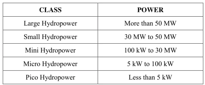
Hydropower plant can be classified according to the size of electrical power produce as shown in table 2.1.
Table 2.1: Classification of Hydropower (Adewoyo, 2009)
CLASS POWER
Large Hydropower More than 50 MW
Small Hydropower 30 MW to 50 MW
Mini Hydropower 100 kW to 30 MW
Micro Hydropower 5 kW to 100 kW
6
However most experts agree that hydropower of more than 1 MW cannot be considered as renewable (K. Sopian et al. 2009). This is due to factors which reducing its capacity after a number of years. Water reservoir or dam also leads to environmental damages and remove people from their roots. While the micro and Pico-hydro may be small compared to hydropower classes of mini to large, they have made significant contribution to remote and off-grid settlements. This small-scaled hydropower provides enough power to light-up the community at night. The system does not require dam, instead it uses run-of-river application through penstock to provide the head and flow rate to the turbine.
A pico-hydro is categorized based on its capability of producing the electricity up to 5 kW. Most of the time there will be a trade-off between head and the flow rate. When the stream is small, meaning the flow rate is low, high head will ensure the turbine to provide enough power as required, and vice-versa.
2.2 STATUS AND APPLICATIONS
Developing countries provide at least 70 percent economically feasible sites for hydropower plant (Bartle, 2002). This is referring to large-scale (mini to large classes) hydropower plant. In Malaysia, there is 2400 MW Bakun project with several other mini hydro worth about 40 MW while technically seen to have another 29000 MW potential of hydropower (Lidula, 2007). However the capability of small-scale hydropower scheme is not included despite the availability of potential sites which could benefit the rural community tremendously.
7
project at Taratak Indonesia, which has been successfully in operation using a head of 5.5 m and discharge rate of 240 l/s (Muhida, 2001). Another in Cameroon, a water turbine of 5 kW capacity with available head of 10 m and flow rate of 92.6 l/s is used to provide 24 V DC system (Nfah, 2009).
Some comparisons between pico hydro and solar powered systems have been made to evaluate the feasibility of the renewable energy resources by Maher et al. (2003) in the off-grid electrification options in rural Kenya. Similar assessment was made by Nunes and Genta (1996) at bigger micro hydro turbine (up to 100 kW) for off-grid electrification program in Uruguay. Both hydro systems are cost effective compared to using the solar panels when the settlements are located near river. Therefore smallscale hydro system should be considered, whenever available, due to cost and environmental concerns (Paish, 2002).
Small hydropower schemes combine the advantages of large hydro on the one hand and a decentralized power supply on the other hand. They do not have many disadvantages, such as environmental issues, and high cost of investment in case of large hydro power plant. Small hydro power plants can be connected to electricity grid. Most of them are run-of-river type; they do not have any sizeable reservoir and produce electricity when water provided by the river flow is available, when river dries up generation cesses. The efficiency of small hydro units are ranging from 60% to 90% while modern coal burning units around 43% to 63% (Wazed and Ahmed, 2008).
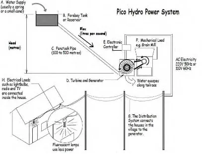
2.3 PICO HYDRO POWER SYSTEM
8
Figure 2.1: Component of Pico Hydro System (Maher and Smith, 2001)
As shown in Figure 2.1, the concept of pico hydropower system can be explained in detail. Firstly from water supply, water will enters the turbine’s system and allow the rotor which includes runner blades to rotate. During rotation, the turbine produces kinetic energy which then converted to electric energy by the generator which attached together with its shaft. Next, once when the generator produces electric energy it is then will be distributed to the houses by the distributer system. Detailed explanation about the pico hydropower system can be referred from A to H.
9
B- The water is fed into a fore bay tank. This is sometimes enlarged to form a small reservoir. A reservoir can be a useful energy store if the water available is insufficient in the dry season.
C- The water flows from the fore bay tank or reservoir down a long pipe called the penstock. At the end of the penstock it comes out of a nozzle as a high-pressure jet.
D- The power in the jet, called hydraulic power or hydro power is transmitted to a turbine runner which changes it into mechanical power. The turbine runner has blades or buckets which cause it to rotate when they are struck by water. The turbine is a general name that usually refers to the runner, the nozzle and the surrounding case. The runner typically spins 1500 times each minute. The turbine is attached to a generator. The purpose of the generator is to convert rotating power into electrical power. This is how the water flowing in a small stream can produce electricity.
E- An electronic controller is connected to the generator. This matches the electrical power that is produced, to the electrical loads that are connected. This is necessary to stop the voltage from going up and down. Without a load controller, the voltage changes as lights and other devices are switched on and off.
F- The Mechanical Load is a machine which is connected to the turbine shaft often using a pulley system so that power can be drawn from the turbine. The rotating force of the turbine runner can be used to directly turn equipment such as grain mills, or woodwork machinery. Although approximately 10% of the mechanical power is lost in the pulley system, this is still a very efficient way of using the power. More power is available because none is lost in the generator or in an electric motor.