APPROVAL
I admit that had read this dissertation and in my opinion this dissertation is satisfactory in the aspect of scope and quality for the bestowal of Bachelor of
Mechanical Engineering (Thermal and Fluid)
Signature : ………
Name of 1st Supervisor : Mrs Fatimah Al-Zahrah Bte Mohd Saat
STUDY ON THE LAMINAR PULSED FLOW IN MICROCHANNEL
RAZIMAN BIN RAMLI
This Report is Submitted in Accordance With The Partial Requirement for the Honor of Bachelor of Mechanical Engineering (Thermal-Fluid)
Faculty of Mechanical Engineering Universiti Teknikal Malaysia Melaka
ii
DECLARATION
“I verify that this report is my own work except for the citation and quotation that the source has been clarify for each one of them”
Signature :………..
iii
DEDICATION
iv
ACKNOWLEDGEMENT
In this great opportunity, I would like to thank Allah for providing me strengths to finish up this project and finally it was completed. Here, I would like to acknowledge with appreciation to all those people who helped me numerously during finish up my project for this year.
In a particular, I would like to express my gratitude to my supervisor, Mrs Fatimah for giving me a chance to do the project under his guide and attention. I also would like to forward my thanks to UiTM for giving me lots of Journal and info during implementation of this project. And not to forget to all panels that evaluated my presentation, a very big thanks to all of you.
v
ABSTRACT
vi
ABSTRAK
vii
TABLE OF CONTENT
CHAPTER TITLE PAGE
DECLARATION
DEDICATION
ACKNOWLEDGEMENT
ii
iii
iv
ABSTRACT v
ABSTRAK vi
TABLE OF CONTENT vii
LIST OF FIGURES x
LIST OF TABLES xi
LST OF SYMBOLS xii
LIST OF APPENDIX xiii
CHAPTER I INTRODUCTION 1
1.1 Background
1.2 Objective
1
3
1.2 Problem Statement 4
1.4 Scope of Study 5
1.5 Project Flow Chart 7
CHAPTER II LITERATURE REVIEW 8
2.1 Microchannel 8
viii
2.2 The Important and Application of
Microchannel
2.3 Flow Channel Classification
10
13
2.4 Problem Related In Microchannel 14
2.5 Fluid Flow And Reynold Number
2.6 Type of Flow
2.7 Laminar Flow
16
17
18
2.8 Pulsed Flow 19
2.9 Computational Fluid Dynamics 21
2.10 Navier Stokes Equations 22
2.10.1 Derivation and Description 23
CHAPTER III METHODOLGY 26
3.1 Introduction 26
3.2 Collecting Information 27
3.3 Physical Domain And Meshing 28
3.4 Boundary Type 32
3.5 User Defined Function (UDF) 34
CHAPTER IV RESULT AND DISCUSSION
4.1 Fluent Result Validation
4.2 Pressure Gradient
4.3 Velocity Magnitude
4.4 Temperature Profile
37 37 37 39 41 CHAPTER V CHAPTER VI DICUSSION CONCLUSION
5.1 Conclusion
5.2 Recommendation
43
44
44
ix
REFERENCES 46
BIBLIOGRAPHY 48
x
LIST OF FIGURES
FIGURE TITLE PAGE
1.1 Schematic of flow through a rectangular duck and the
coordinates system.
5
1.2 Flowchart for the whole project 7
2.1 Microchannel Cooling System 12
2.2 Dye filament with straight line 18
3.1 Flowchart for the Methodology 27
3.2 Origin of the Cartesian coordinate system 28
3.3 Isometric view cross-section for microchannel 29
3.4 Overall meshing for microchannel 31
3.5 Boundary type of the Microchannel 33
3.6 4.1 4.2 4.3 4.4 4.5
The UDF file for the pressure pulsating flow
Pressure at inlet plane microchannel
Pressure at outlet plane microchannel
Velocity vs. time at inlet plane microchannel
Velocity vs. time at outlet microchannel
Temperature vs. time at inlet and outlet microchannel
xi
LIST OF TABLE
TABLE TITLE PAGE
2.1 Channel Classification Scheme. 13
xii
LIST OF SYMBOLS
VLSIC = Very Large Scale Integrated Circuit
ULSIC = Ultra Large Scale Circuit
ReLRe,R,
ReD, ReR
= Reynold Number in varius of length
IC engine = Ignition Combustion engine
= Density, kg/m3
V = average fluid velocity
V = mean fluid velocity, m/s
= kinematic viscosity, m²/s
L = characteristic length, m
Dx, = Length for x-axis
Dy = Length for y-axis
Dz = Length for y-axis
mf = Mass flux
u = Velocity in x direction, m/s
DA = Surface Area, m2
SFx = Sum Of The External Forces
FH,Fx,Fy,Fz = Force, N or kg m/ s²
gx = Gravity, m/ s²
Q = Flow rate
xiii
APPENDIX
NO TITLE PAGE
A Modelling laminar pulsed flow in rectangular
microchannel
1
CHAPTER I
INTRODUCTION
Chapter I are focusing on the project background, project objectives, and
problem statements, scope of work and flow of the project.
1.1 Project Background
Another class of flow channels that have received some attention in literature are
those with hydraulic diameters below 600 µm. These channels are referred to as
microchannels. There are very few quantitative studies available for the microchannel
geometry under laminar pulsed flow. Further efforts are needed in this area to generate
high-quality data in microchannels under in laminar pulsed flow.
Laminar flow through rectangular ducts is important in various fields such as
microfluidic devices, and many papers have been devoted to solutions for steady and
unsteady flows in rectangular channels under different pressure gradients. For steady
state fully developed laminar flow of a viscous incompressible fluid, the theoretical
solutions for the velocity profile are well recognized, see e.g. Fan and Chao (1965),
Round and Garg (1986) and Spiga and Morini (1994). For fully developed oscillatory
2
analytical solutions for the velocity for the cases of small and large values of frequency.
Yakhot et al. (1999) also considered oscillatory flow under sinusoidal pressure
gradients, and numerically analyzed velocity distribution and wall shear stress. Both of
the above studies restricted their analysis to harmonic flows only and did not consider
transient responses to imposed pressure gradients, which we believe was first reported
by Fan and Chao (1965). They obtained an exact analytical solution for the velocity of
transient flow under an impulse pressure gradient, i.e., the Green function for the
velocity. They applied it to obtain solutions for the velocity under any pressure gradient
by convolution and analyzed the velocity distribution under a purely harmonic pressure
gradient. Flow through arbitrary-shaped ducts including rectangular channels under any
pressure gradient has also been considered by Ray and Durst (2004), who presented
semianalytical solutions.
This brief discussion of the literature shows that velocity distributions have been
widely investigated and the solutions can be used to study various flow effects in
rectangular channels. For example, flow reversal under a purely harmonic pressure
gradient was discussed by Fan and Chao (1965) and Yakhot et al. (1999), and phase
shifts of velocity and wall shear stress with frequency approaching infinity or zero were
predicted using asymptotic solutions (Yakhot et al., 1999). Local wall shear stress is an
important factor in the formation, mitigation and removal (cleaning) of fouling layers on
the surface of process equipment and particularly heat exchangers. Fouling is a common
and major problem for many processes including microfluidic devices such as microheat
exchangers. Rectangular microchannels produced by mechanical cutting or etching
techniques are widely used in microfluidic heat exchangers.
Rectangular microchannels produced by mechanical cutting or etching
techniques are widely used in microfluidic heat exchangers (Brandner et al., 2007). The
channels are prone to fouling due to their small characteristic dimensions, resulting in
laminar flow with low velocity and low local wall shear stress. Fouling often increases
thermal resistance and pressure drop, leading to decreased rates of heat transfer and
3
Pulsed flow, where pulsations are imposed on a steady flow, presents a possible
mitigation method and its efficacy as a cleaning method has been demonstrated
experimentally (Augustin and Bohnet, 1999; Gillham et al., 2000; Bode et al., 2007).
The shear stress imposed by the fluid on the surface plays an important role in both
formation and removal of fouling deposits: flow pulsation represents a method for
enhancing this property without using higher flow rates continuously. Celnik et al.
(2006) recently employed the Green function method to obtain solutions for laminar
pulsed flow in circular and annular ducts and quantitatively discussed the wall shear
stress enhancement. However, little theoretical work on local wall shear stress and its
enhancement in rectangular channels by pulsed flow has been reported.
1.2 Project Objectives
This part will discuss deeply about the project objectives. This project is
developing with the following objectives:
(a) To computationally simulate laminar flow in rectangular microchannel
by using Computational Fluid Dynamics (CFD) software. There are many types
of CFD software, but for this project GAMBIT version 2.2 and FLUENT version
6.2 are used.
(b) To study and understand on how to create and meshing geometry in
GAMBIT and selecting the right solver to compute in FLUENT and know how
to use both software effectively.
(c) To study on microchannel characteristic and the application in this new
4
(d) To study the pulsed flow and pressure drop in single phase rectangular
microchannel.
1.3 Problem Statements
This work has been carried out to do research work on fouling mitigation and
cleaning enhancement in process equipment, which is a major problem in several
industry sectors. For example, dairy heat exchangers often have to be cleaned daily and
downtime can be in excess of 40% of available process time (Gillham et al., 2000).
Many units subject to fouling, particularly in the food sector, employ cleaning-in-place
systems where a cleaning fluid is circulated through the system: the cleaning agent
converts the surface fouling layer to a form which is more readily removed by hydraulic
or diffusive processes. In many dairy applications, aqueous solutions of sodium
hydroxide are employed as these cause proteinaceous deposits to swell and weaken. In
the interests of hygiene and to avoid contamination of the product such cleaning agents
must be purged from the system before the system can be reused. It is therefore
pertinent to optimize the cleaning cycles to give both environmental and economic
improvement.
Past studies have used a variety of techniques to improve the cleaning of
whey-protein and dairy systems. Gillham (1997) studied the effect on cleaning of imposing
flow pulses on a steady laminar flow through cylindrical pipes. Pulsing has the effect of
raising the maximum shear stress at the pipe wall, thus increasing the cleaning rate
(Gillham et al., 2000). High values of wall shear stress can also be achieved using larger
flow velocities and are used in some commercial cleaning-in-place systems to reduce
cleaning time. Gillham et al. (2000) showed that the same effect may be achieved at
lower velocities by using pulsation, which may be advantageous in systems where the
inventory of cleaning agent is to be minimized, the liquid is very viscous, or velocity
5
laminar flow is of interest. In Malaysia, the application usage of minichannel and
microchannel still not wide. Many of cooling component still used channel (3mm and
above) as a transportation of fluid. For example, many of server room using
air-conditioning to cooled the temperature of the room so that it will cool the computer
server unit.
1.4 Scope of Study
This project will concentrate on simulating laminar flow in rectangular
microchannel. This concept and the correct calculation must be known to get the correct
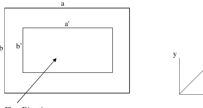
[image:19.612.185.511.360.534.2]value for each parameter that has been studied. The detailed scope for this project is:
Figure 1.1 Schematic of flow through a rectangular duck and the coordinates
system.
(a) We consider fully developed laminar flow in a duct of rectangular cross-section
of width a = 0.8 milimeter and height b = 0.8 milimeter respectively. The length
c = 5 milimeter for fluid region, and for the solid region, the cros-section of Flow Direction
b
a
y z
x a'
6
width a’ = 0.4 milimeter, height b’ = 0.4 milimeter respectively and the length is
c’ = 5 milimeter.
(b) The fluid is incompressible and Newtonian with constant physical properties;
natural convection and gravity are negligible and the pressure gradient is
non-zero in the z-direction only; changes to the pressure gradient are effectively
instantaneous throughout the system; velocities in the x and y directions are zero.
(c) Three Dimension rectangular duct geometry (3-D) is simulated Fluent 6.2
software using three dimension double precision (3DDP).
(d) This study only considers a single phase flow condition. The application of
single-phase heat transfer enhancement in conventional sized passages has been
7
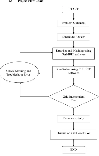
[image:21.612.81.464.76.680.2]1.5 Project Flow Chart
Figure 1.2: Flowchart for the whole project START
Problem Statement
Literature Review
Drawing and Meshing using GAMBIT software
Run Solver using FLUENT software
Grid Independent Test
Parameter Study Check Meshing and
Troubleshoot Error
Discussion and Conclusion
8
CHAPTER II
LITERATURE REVIEW
Chapter II is about the literature review that regarding to the project. It contains
methods to do research, theory used to solve problems in this project and so on.
2.1 Microchannel
Over the past 10 years, micromachining technology has been used to develop a
number of microfluidic systems in silicon, glass, quartz, or plastics. Microchannels and
chambers are the essential part of any such system. In addition to connecting different
devices, microchannels are also used for reactant delivery, as biochemical reaction
chambers, in physical particle separation, in inkjet print heads, or as heat exchangers for
cooling computer chips. Currently, fluid flows in microchannels and microma-chined
fluid systems like pumps and valves are analyzed using the Navier–Stokes equations.
However number of publication indicated that flows on the microscale are different
from that on the macroscale and that the Navier–Stokes equations are incapable of
explaining the occurring phenomena. Thus, in order to design and fabricate such micro
devices effectively, the fluid flow on the microscale must be understood. The first
studies of fluid flow on the micro scale were performed by Wu and Little (1983 and
1984). They conducted experiments measuring Darcy friction factors for both laminar
and turbulent gas flow in microchannels to evaluate the performance of Joule Thompson
9
diameters ranging from 50 to 80 mm. The observed Darcy friction factors were larger
than predicted by classical macroscale theory (Ian Papautsky et al. 1998).
Addition, microfluidic system in miniaturized devices have found application in
many areas such as chemical processes, propulsion and power generation, cooling of
electronic devices, aerospace industry, inkjet printers, and biomedical industry. In case
of microdevices, the continuum approach can still be applied for modeling fluid flow,
especially if the fluid is liquid. However, there are many situations where fluid flow
behavior in microdevices can considerably deviate from those in macroscopic devices.
The characteristic dimension of a microchannel within a microfluidic system is in the
range of 1–1000 lm. The Reynolds numbers encountered in microfluidic systems are
quite small (often on the order of 1.0 or smaller). Surface forces, which originate due to
intermolecular forces, could be important in microchannel flows. These forces are
generally ignored at macroscale. Surface effects also alter the value of viscosity. It is
found that the apparent viscosity is lower in the narrower channel, which is contrary to
the expected trend. Another important effect is air-dampening, which could directly
influence quality factor of the devices. The strong air dampening is due to the dramatic
increase in the surface- to-volume ratio. Due to large surface-to-volume ratios in
microdevices, both convective and radiative heat transfer rates are enhanced
considerably. Despite deviation of flow behavior at the microlevel, one should carefully
analyze to see if the continuum approach is valid in a given microfluidic device (Tuba
10
2.1.1 Type Flow In Microchannel
Fluid is transported in several ways in the microchannels used in microfluidic
devices. Two important methods of transport are flows driven by pressure differential
and electro-osmotic flows. In the former case, flow is transported by means of applied
pressure differences. In the latter case, flow transport is initiated by application of a high
electric field. This type of flow is broadly classified as electrokinetic’s flow. Capillary
driving forces owing to surface tension, ‘‘wetting’’ of surfaces by the fluid, can also
lead to pressure gradients in liquids. This pressure gradient causes flow transport, so it is
similar in many ways to pressure driven flows. However, the shape of the interface is an
important factor in this type of flow. Free surface flows are caused by gradients in
interfacial tension (Marangoni flows). These can be manipulated using the dependence
of surface tension on temperature or chemical concentration (Tuba Bayraktar, Srikanth
B. Pidugu, 2006).
2.2 The Important and Application of Microchannel
Microstructure technology has practical applications in many fields, including
bioengineering and biotechnology, aerospace, mini-heaters and mini-heat exchangers,
materials processing and manufacturing. For example, microchannels and mini-heat
exchangers with flow channels having dimensions ranging from several hundred
microns to 0.1/µm have found application in bioreactors for the modification and
separation of biological ceils and selective membranes. In addition, microstructure
technology may provide new tools for examining more closely physical phenomena and
may result in the development of a method or methods by which thermal phenomena,
often considered very difficult or impossible to investigate due to the small length scale,
can now be studied. These suggest the types of creative and innovative applications that