Development of PV and TEG Integrated Charging System for Rechargeable Lithium Ion Battery for Hybrid Car
WAN AKMAL SYAHIRAN BIN WAN AHMAD
A report submitted in fulfillment of the requirement for the degree of Bachelor of Electrical Engineering (Industrial Power)
Faculty of Electrical Engineering
UNIVERSITI TEKNIKAL MALAYSIA MELAKA
I hereby declare that I have read through this report entitle “Development of PV and TEG Integrated Charging System for Rechargeable Lithium Ion Battery for Hybrid Car” and found that it has comply the partial fulfilment for awarding the degree of Bachelor of Electrical Engineering (Industrial Power)
Signature : ………
Supervisor’s Name : En. ZUL HASRIZAL BIN BOHARI
I declare that this report entitle “Development of PV and TEG Integrated Charging System for Rechargeable Lithium Ion Battery for Hybrid Car” is the result of my own research excepts as cited in the references. The report has not been accepted for any degree and is not concurrently submitted in candidature of any other degree.
Signature : ………
Name : WAN AKMAL SYAHIRAN BIN WAN AHMAD
i
ACKNOWLEDGEMENT
Assalamualaikum warahmatullahi taala wabarakatuh,
ii ABSTRACT
iii ABSTRAK
iv
TABLE OF CONTENTS
CHAPTER TITLE PAGE
ACKNOWLEDGEMENT i
ABSTRACT ii
TABLE OF CONTENTS iv
LIST OF TABLES vii
LIST OF FIGURES viii
LIST OF APPENDICES ix
1 INTRODUCTION 1
1.1 Introduction 1.2 Background 1.3 Problem Statement 1.4 Motivation
1.5 Objectives
1.6 Scope Of Projects 1.7 Project Conclusion
1 2 3 3 4 5 5
2 LITERATURE REVIEW 6
2.1 Introduction
2.2 Overview of Photovoltaic System and Earlier Researches
2.3 Principle of Solar Cell 2.4 Structure of a Solar Cell 2.5 Crystalline Silicon (c-Si)
2.5.1 Mono-crystalline Silicon Solar Panel 2.5.2 Poly-crystalline Silicon Solar Panel
v 2.6 Thin-Film
2.6.1 Amorphous Silicon Solar Cell
2.6.2 Cadmium Telluride Solar Cell (CdTe) 2.7 Backup Battery
2.7.1 Nickel Cadmium (NiCad) 2.7.2 Nickel Metal Hydride (Nil MH) 2.7.3 Lithium ion (Li-ion)
2.8 How Hybrid Cars Work
2.9 Thermoelectric generator work 2.10 Summary of Literature Review
14 15 16 17 17 18 18 18 19 20
3 METHODOLOGY 21
3.1 Introduction 3.2 Project Flow Chart 3.3 Planning
3.3.1 Literature Review
3.3.2 Determination type of PV cell that will be selected to design
3.3.3 Investigate on designing hardware 3.4 Construct
3.4.1 Design and construct the hardware
3.4.2 Testing the project and analysis data based on related theories
3.5 Analysis 3.6 Report writing
21 22 23 23 23 25 25 26 27 28 28
4 RESULT 29
4.1 Introduction
4.2 Result from Prototype Model (hardware) 4.3 Measurement and Calculation value
4.4 Result from Past Research about Performance of Transparent Solar Panel
4.4.1 Calculation
29 30 34 36
vi
4.4.2 Analysis & Discussion 38
5 CONCLUSION 40
5.1 Conclusion 5.2 Achievement 5.3 Recommendation
40 41 41
REFERENCES 42
vii
LIST OF TABLE
TABLE TITLE PAGE
3.1 Specifications of Solar Module 24
4.1 Data Sheet of Amorphous Silicon 1W 6V Flexible Solar Panel 34
4.2 Measured Value of Flexible Solar Panel 34
4.3 Measured Value of Thermoelectric Generator (TEG) 35 4.4 Parameters of Tested Microcrystalline Silicon Carbide Thin
Films Cell
viii
LIST OF FIGURE
FIGURE TITLE PAGE
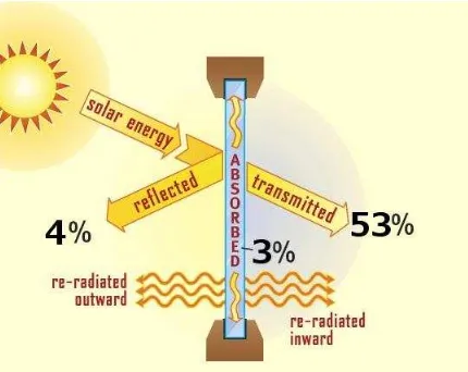
1.1 Windshield surface receives solar radiation 3
2.1 Arrangement of PV Cell, Module and Array [3] 7
2.2 Typical Solar Cell Structure [4] 9
2.3 Structure of Silicon Atom bonds with four other atoms [5] 10 2.4 Number of P-type and N-type Silicon Atom Electron [5] 11
2.5 Mono-crystalline Silicon Solar [7] 12
2.6 Polycrystalline Solar Cell [6] 13
2.7 Amorphous Silicon Solar Cell 15
2.8 Cadmium Telluride (CdTe) Solar Cell 16
2.9 Thermoelectric generator configurations 19
3.1 Project flowchart of the “Development of PV Integrated Charging System for Rechargeable Lithium Ion Battery for Hybrid Car”
22
3.2 The general electrical system of the solar car. 24
3.3 Design charging Li-ion battery 26
3.4 The Structure of Designed Model of prototype version in Solid
Work 27
4.1 The foundation of hardware for stand the glass and roof in Solid Work
30
4.2 The Framework of hardware were assembled 31
ix
LIST OF APPENDICES
APPENDIX TITLE PAGE
A Myipo’s Patent Customer Copy 44
B Certificate of Participation in iCompex’15 45
C Certificate of Participation in iEnvex2015 46
D Poster of iCompex’15 Exhibition 47
E Poster of iEnvex2015 Exhibition 48
1
CHAPTER 1
INTRODUCTION
1.1.1 Introduction
Hybrid cars productions today are marketed by two major benefits, which are increased fuel economy and reduce greenhouse gases emission. Generally, hybrid cars produce 80% less harmful pollutants and greenhouse gases than comparable gasoline cars. This translates to eco-friendly system, and a cleaner earth. A hybrid car is driven by a hybrid engine, which is any engine that combines two or more sources of power, generally gasoline and electricity. Hybrid systems use batteries to store the sources of power to make the vehicle move, while braking system use to generate kinetic energy so that the batteries can recharged while driving [1]. In this report, the implementation of transparent solar panel to replace all windshield glass in hybrid car in order to be a part of electrical source system for charging the batteries.
2 To begin the project, an alpha version of a prototype (hardware) needs to construct to study the performance of solar panel with respect to the sun radiation and its contribution (energy consumption).
1.2.1 Background
The sun is known to supply the world with a permanent and abundance clean energy source in the form of solar radiation. The measure of sun oriented radiation captured by the world's surface is 82×1015 W which is much higher compared to the annual global energy use [2]. Understanding this, researches have been widely done lately producing many promising technologies in order to extract the sun‟s energy. Hybrid car have currently been introduced to the market. These hybrid cars have components such as a computer, inverters, a battery, and electric traction motors which can readily use photovoltaic generated electricity to produce propulsion.
3 1.3 Problem Statement
Energy policies and global warming have become a hot topic on the international issue. Advanced countries are trying to lessen their greenhouse gas outflows. Clean energy can be produce by a technological alternative such as renewable energy source. Over the renewable energy, photovoltaic system has received a big attention as it appears to be one of the most promising zero emission. Solar modules to vertical walls or facades had been widely used to produce energy. To avoid pollution caused by fossil fuels from the cars and to save fuel cost, hybrid system is the one of the best way to be installed for car. For construct model of the system, it required to understand the operation of solar system to meet the specification of hybrid car system. Lot of fundamental engineering knowledge is needed to begin this project.
1.4 Motivation
[image:15.612.223.438.484.655.2]The car‟s windshield surface, which receives up to 60% of the solar radiation incident upon the vehicle glazing, is traditionally tinted, resulting in absorption but produce nothing. When solar radiation hits the car glass windows, 4% of radiation is reflected off the glass, another 3% absorbed by the glass, and 53% transmitted through the glass shows in figure 1.1.
4 For these reasons, it is needed to design a PV integrated power source, to replace windshield glass so that it will utilize the wasted energy generated by sun to produce electrical energy to charge a battery of hybrid car. It is can be a new part of electrical source systems to improve the charging system in hybrid car. Before, hybrid car might have braking system to utilize kinetic energy or dynamo to generated electricity by rotation of tires or maybe solar panel on the roof top, but now then system will improved by installing the transparent solar panel for all glasses to optimize day light energy for charging the batteries during parked or driving under the sun. The motivation of this thesis, develop a photovoltaic solar panel in windshield glasses so that it will utilize the wasted energy produced by sun to produce electrical energy for charging a battery of hybrid car. It will be new part of electrical source system to improve the charging rate while generating clean electricity and eco-friendly system.
1.5 Objectives
Design and analysis of photovoltaic integrated charging system are the aims of the research. The photovoltaic integrated should be capable to meet specification of battery such as output power, voltage, and current. To achieve these aims, the objectives of this research are to:
I. Analyze the output value from model of solar charging system with using related theories and formula.
II. Analyze the operation of transparent solar panel that will be installing for charging system in hybrid car.
5 1.6 Scope Of Projects
The scopes of this project are:
I. Developing a model of photovoltaic module that converts solar energy to electric energy.
Design a prototype of electrical system for charging batteries in small scale. Use batteries bank as a storage unit and solar panel as a generating system. II. Determination type of photovoltaic cell that will be designed.
Study on the best type of photovoltaic cell for windows which are needs to be transparent and efficient. Understanding the suitable type of solar panel that can be selected.
III. Research on battery chemistries that suitable for hybrid car that can be able for solar panel to store the energy.
Investigate the suitable type of batteries used by electric motor of hybrid car. The percent of charged energy input by solar panel daily.
1.7 Project Conclusion
6
CHAPTER 2
LITERATURE REVIEW
2.1 Introduction
Today, hybrid electric vehicles are chosen for the option of the day and many automobile companies have their interest and asset in this area. The main reasons for this are for the coming energy crisis, and significant increase of greenhouse gases. The proposed system can produce power, without polluting the air.
Thus this chapter will explain development an electrical source system for electric or hybrid car which includes the solar panel and batteries as its input energy sources and the power electronic devices as connecting and transforming part. The transparent solar which is mounted with windshield absorbs solar energy during the day time to supplement energy cost of battery.
7 2.2 Overview of Photovoltaic System and Earlier Researches
Photovoltaic cells are available in the market with different semiconductor materials. The most popular semiconductor materials for PV are monocrystalline, polycrystalline, thin film and copper‐indium selenide (CIS). The technologies involved of p‐n junction diodes capable of generating electricity from light sources and usually have efficiencies of 6% ‐ 20% in market use [1].
Making of Monocrystalline and polycrystalline silicon arrays are almost the same way. There are made up of individual 0.5 V cells connected together to achieve the required power [1]. Their weigh less than the amorphous and CIS arrays, and are about half the size of CIS arrays in which to produce the same power.
Microcrystalline silicon carbide (μc-SiC:H) thin film, CIS thin film and amorphous thin film are the most popular type of Thin Film PV technologies. Thin film be made up of a layer of silicon fabricate with glass and plastic [2]. ]. A laser scribe is then used to mark out individual cells. Thin film cell generate very good energy consumption on sunny days compare to other crystalline silicon cell. However thin film need to be bigger in size than other crystalline silicon cell in way to produce the same energy.
[image:19.612.167.457.510.634.2]Basically one single cell can produces about 0.5 volt and then they are connected together to form modules (combination of 36 cells). Combination connected of modules can form larger units called arrays as shown by Figure 1.1.
8 2.3 Principle of Solar Cell
A photovoltaic or solar panel is made up of several photovoltaic solar cells. A cell of photovoltaic normally generates about 1 or 2 watt of power [3]. Energy is generated when photons of light from the sun collides a solar cell and are captivated inside the semiconductor material. This energizes the semiconductor‟s electron, result in the electrons to discharge, and produce an electric current [3]. The electricity generated is direct current (DC) since the flow of charge is in one direction. To increase the output power of PV cells, they are connected together to form larger units. This joined cell is call array, and the combination between arrays are called module. Producing module is to produce more power, and so on. Therefore, photovoltaic systems can be built to meet all electric power need, small or large.
2.4 Structure of a Solar Cell
Solar panels, from the very small ones used in some calculators, to the much larger ones found on some suburban rooftops, are made up of various numbers of photovoltaic cells. These cells, also known as solar cells, make use of a natural energy source, the sun, to generate electrical power without any moving parts, noise, pollution, radiation or the need for maintenance [5]. A solar cell is formed by a composition of materials typically made up of the following layers:
I. Glass cover with anti-reflective coating II. Front contact grid
III. N-type (negative) silicon IV. P-type (positive) silicon
9
Picture 2.2: Typical Solar Cell Structure [4]
10 2.5 Crystalline Silicon (c-Si)
[image:22.612.175.449.243.376.2]The popular choice of solar cell material is silicon because it‟s inherent physical quantities. Silicon has 4 valence electrons from an 8 „holes‟. It will always attract to fill the other 4 „holes‟, thus the hole will sharing electrons with another silicon atoms [5]. A lattice type structure then created after the sharing proces, where every atom in the structure bonds with four other atoms in the structure.
Figure 2.3: Structure of Silicon Atom bonds with four other atoms [5]
Under the sun emission days, energy is added to silicon material. Then the electron will be knock out and free from lattice structure, but this proces need a lot of energy and produce very few free electron. As the free electron release from lattice, there is small current flow. Therefore, some impurities are added to increase its current. The process of added impurities to the silicon is called doping process [5].
11
Figure 2.4: Number of P-type and N-type Silicon Atom Electron [5]
12 2.5.1 Mono-crystalline Silicon Solar Panel
[image:24.612.198.427.278.444.2]Single silicon crystal can form a Mono-Crystalline panel. Silicon crystal can get either made in a laboratory of found naturally (hard to find). Process of create this crystal is called recrystallizing, which is tough to produced and then will make the Mono-crystalline panels more expensive. The interface of Mono-Crystalline is smoother than poly- Crystalline panel, as shown in figure 2.5. Normally Mono-Crystalline efficiency is around 15% at 25°C, and then drops at 50°C by 12% to 15% [7]. Therefore, the higher temperature of the panel gets, the lower the efficiency of the solar panel.
![Figure 2.1: Arrangement of PV Cell, Module and Array [3]](https://thumb-ap.123doks.com/thumbv2/123dok/506718.57279/19.612.167.457.510.634/figure-arrangement-pv-cell-module-array.webp)
![Figure 2.3: Structure of Silicon Atom bonds with four other atoms [5]](https://thumb-ap.123doks.com/thumbv2/123dok/506718.57279/22.612.175.449.243.376/figure-structure-silicon-atom-bonds-atoms.webp)
![Figure 2.4: Number of P-type and N-type Silicon Atom Electron [5]](https://thumb-ap.123doks.com/thumbv2/123dok/506718.57279/23.612.114.514.76.244/figure-number-p-type-type-silicon-atom-electron.webp)
![Figure 2.5: Mono-crystalline Silicon Solar [7]](https://thumb-ap.123doks.com/thumbv2/123dok/506718.57279/24.612.198.427.278.444/figure-mono-crystalline-silicon-solar.webp)