CHAPTER II LITERATURE REVIEW
2.1. Irrigation
Irrigation is defined as the process of artificial application of water to the soil in order to reach these following objectives: ensure enough moisture for agricultural crop growth, provide crop insurance against short duration drought, reduce hazards of soil piping, soften the tillage pan (a dense compact layer), cool the soil and atmosphere to provide a good atmosphere for plant growth, and wash out or dilute harmful salts in the soil (Mazumder, 1983; Basak, 1999; and Misra, 1981).
2.2. Crop Pattern
The Regulation of Kebumen Regent (2010) suggests crop pattern for each irrigation area to be adjusted with the supply of irrigation water condition
a. When irrigation water is sufficiently available, the crop pattern is paddy-palawija.
b. When irrigation water is moderately available, the crop patter is paddy-paddy-palawija or paddy-paddy-palawija-palawija.
2.3. Irrigation Canal
Misra (1981) proposed three requirements of irrigation canals. 1. The canal should be non-silting and non-eroding.
2. The water flows gravitationally.
3. The canal should have no water-logging by the presence of proper drainage.
The Irrigation and Drainage Design Report (1979) requires standard details of irrigation canals consist of alignment, cross section, and design parameters. In irrigation and drainage, FAO (n.d.) recommends trapezoidal cross section as the most common one to be used. It is applied to the canals in Kedungsamak Irrigation Area.
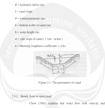
The canal design follows the Strickler or Manning formula (Eq. 2.1-2.6) and the parameters of canal is shown in Figure 2.1.
(Eq. 2.1)
(Eq. 2.2)
(Eq. 2.3)
(Eq. 2.4)
(Eq. 2.5)
(Eq. 2.6)
Notes:
Q = canal discharge (m3/s)
A = cross section (m2)
k = Strickler roughness coefficient (m1/3/s)
R = hydraulic radius (m)
I = canal slope
P = wetted perimeter (m)
b = bottom width of canal (m)
h = water height (m)
m = side slope of canal ( 1 vert : m hor )
[image:3.595.89.511.157.590.2]n = Manning roughness coefficient = (1/k)
Figure 2.1. The parameters of canal
2.3.1. Steady flow in open canal
Chow (1992) explains that water flow with velocity and discharge are constant with respect to time is classified as steady flow. Steady flow in open canal can be divided into uniform flow and non uniform flow. If the water velocity and cross section of canal are changing in every segment, it is classified as non uniform flow.
(Eq. 2.7)
(Eq. 2.8)
(Eq. 2.9)
(Eq. 2.10)
Notes:
yc = critical depth (m) yn = normal depth (m) Q = canal discharge (m3/s)
B = bottom width of canal (m)
m = side slope of canal ( 1 vert : m hor )
R = hydraulic radius (m)
f = slope of water surface profile
A = area of orifice (m2)
I = canal slope
n = Manning roughness coefficient (1/k)
x = distance (m)
2.4. Conveyance Structures
aqueducts, culverts, flumes, and drop or chute structures. There are some general equations related to conveyance structures. They are:
1. Velocity in conveyance structure
Based on KP-04 Bangunan Irigasi (1986), in order to prevent the standing waves happen at the water surface and prevent the flow does not become critical because the canal roughness is less or more steep than the hydraulic gradient, so Froude number should be less than or equal to 0.5 as shown in Eq. 2.11.
(Eq. 2.11)
Notes:
Fr = Froude number
va = Average velocity in the building, m/s g =gravity acceleration, m/dt2 (=9.8)
A = wetted area, m2
B = width of water surface, m 2. Loss because of friction
The loss of friction in conveyance structure can be determined by using Eq. 2.12.
(Eq. 2.12)
Notes:
L = length of building, m
R = hydraulic radius, m (A/P)
A = wetted area, m2
P = wetted perimeter, m
C = Chezy coef. (=kR1/6)
k = Strickler roughness coef., m1/3/s (see Table 2.1)
[image:6.595.89.512.138.546.2]g = gravity acceleration, m/dt2 (=9.8)
Table 2.1. The value of k
Material k (m1/3/dt) Concrete steel
Concrete, Wood, Not finished Steel
Stone masonry
76 70 80 60 Source : KP-04 Bangunan Irigasi (1986)
3. Loss of Energy on the Transitional
Discussing transition in the open canal where Froude number is less than 0.5, energy loss at the in-transition and out-transition is obtained by Borda Equation (Eq. 2.13 and Eq. 2.14):
(Eq. 2.13)
(Eq. 2.14)
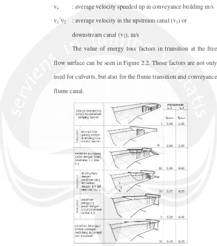
ξ in’ out: energy loss factor depends on the transitional hydraulic
in-transitional (upstream) or out-in-transitional (downstream) as shown in Figure 2.2.
va : average velocity speeded up in conveyance building m/s
v1’v2 : average velocity in the upstream canal (v1) or
downstream canal (v2), m/s
The value of energy loss factors in transition at the free flow surface can be seen in Figure 2.2. Those factors are not only used for culverts, but also for the flume transition and conveyance flume canal.
[image:7.595.86.510.163.644.2]Source: Bos and Reinink, 1981; and Idefcik, 1960 in KP-04 Bangunan Irigasi (1986)
2.4.1. Culvert
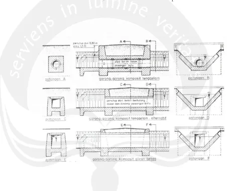
The KP-04 Bangunan Irigasi (1986) explains that culvert has cross section smaller than wetted area of upstream and downstream canal (see Figure 2.3). Parts of cross section might be higher than water surface. In this case, culvert behaves free flow open canal.
[image:8.595.89.541.235.616.2]Source : KP-04 Bangunan Irigasi (1986)
Figure 2.3. Small crossing (Culvert)
reinforcement plate as the lid. The first type is used for big discharge or if impermeable culvert is required. Masonry stone culvert with concrete reinforcement plate is very strong and easy to construct. Especially, in remote area, this culvert is ideal. Figure 2.4 shows types of culvert explained above.
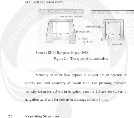
[image:9.595.86.532.224.619.2]Source : KP-04 Bangunan Irigasi (1986)
Figure 2.4. The types of square culvert
Velocity of water flow applied in culvert design depends on energy loss and geometry of in-out hole. For planning purposes, velocity taken for culvert in irrigation canal is 1.5 m/s for culvert in irrigation canal and for culvert in drainage canal is 3 m/s.
2.5. Regulating Structures
examples of regulating structures are headworks structure, checks, turnout structures, diversion structures, and flushing structure.
2.6. Water Measurement Structures
For efficient management of irrigation systems and proper distribution of water, it is necessary to install measurement structures at appropriate locations in the irrigation canal. The examples of water measurement structures are parshall flumes, weirs, and Romijn gate (Irrigation and Drainage Design Report, 1979).
2.7. Protective Structures
The Irrigation and Drainage Design Report (1979) explains that the purposes of constructing protective structures in an open irrigation system are to protect the upstream canal from storm of runoff and to protect the canal from excess rainfall or misoperation of the canal system. The protective structures generally constructed are cross-drainage structures and wasteway structures.
2.8. Other Structures
Based on the Irrigation and Drainage Design Report (1979), these include tunnels, bridges, fish screens, fish ladders, and silt ejectors.
2.9. Design Implementation and Deviation
According to Morardet, S. (2005), weaknesses in planning and implementation (P&I) have been identified as one of the main reasons for
the disappointing results of agricultural water development and
management projects. Therefore, the implementation should represent the
design. The deviations in the existing condition will give influence
directly or indirectly to the design.
2.10. Rehabilitation
The Irrigation and Drainage Design Report (1979) proposes that the existing structures in the system may be capable to perform their functions without much modification, but in many cases they may require major or minor repairs and complete replacement in some cases.
According to the problem that occurred such as leakage at the upstream and downstream ends of flume, the flume should be “sealed
with rubber sheets to ensure no leakage from the sides” (Alhamid,
1996).