Modeling of Flywheel Hybrid Powertrain to Optimize Energy
Consumption in Mechanical Hybrid Motorcycle
Muhammad Zaidan Abdul Manaf
1,a, Nik Abdullah Nik Mohamed
2,b,
Mohamad Shukri Zakaria
1,c, Mohd Noor Asril Saadun
1,d,
and Mohd Hafidzal Mohd Hanafi
1,e1
Faculty of Mechanical Engineering, UniversitiTeknikal Malaysia Melaka, 76100 Durian Tunggal, Melaka, Malaysia
2
Faculty of Engineering and Built Environment, Universiti Kebangsaan Malaysia, 43600 UKM, Bangi, Selangor, Malaysia
a
[email protected], [email protected], [email protected],
d
[email protected], [email protected]
Keywords: Flywheel Hybrid Motorcycle, Flywheel, Power Transfer Efficiency (PTE), Power Conversion Efficiency (PCE) and Back Trace Simulation.
Abstract. The creation of internal combustion engine is a significant milestone in power
engineering world which simplified high mechanical energy demand jobs like moving vehicle and machinery. Even though the internal combustion engine gives lot of advantages, however, this type of engine is incapable to convert the heat energy from fuel combustion to the mechanical energy efficiently. Small capacity engine e.g. motorcycle engine having the power conversion efficiency between 25-30%. Therefore, alternative power source is required to support the internal combustion engine in order to increase the overall system efficiency. These phenomena give encouragement to implement the hybridization process. This is to increase the system efficiency in transferring power to the wheel. Hybridization processes e.g. flywheel as secondary power source can increase power transfer efficiency between 30%-80%. Hence, the purpose of this research is to develop the mathematical model of the power transfer efficiency of flywheel hybrid motorcycle by using back trace simulation method. This model will record the amount of energy use in acceleration phase of the driving cycle. Subsequently, the efficiency ratio of motorcycle power transfer is calculated and comparison of those ratios between the conventional motorcycle and the hybrid motorcycle is made. The outstanding results show that the hybrid motorcycle is capable to conserve the energy used up to 36% compare to the conventional motorcycle that wasted energy up to 200%. As a conclusion, flywheel as the secondary power source is capable to supply enough energy to propel the motorcycle forward.
Introduction
The concept of flywheel hybrid powertrain is originated from kid’s toys car. It is used small metal disk known as flywheel to store the kinetic energy transmitted from the wheel during the push action. When release, the store kinetic energy inside the flywheel is transfer back to the wheel and propel the toys car forward. Two concepts gathered from these simple innovations which are the regenerative braking concept and the power propulsion concept. Above all, it does not involve any chemical and electrical concepts. It is totally harnesses the power of mechanical energy. Therefore the same concepts is used in full scale motorcycle to reduces internal combustion engine contribution in propel the motorcycle forward.
Furthermore, the concept of using flywheel as alternative power source in vehicle is parallel with global initiative to reduce harmful carbon release to atmosphere. In Asian country, motorcycle is the most famous transportation device cause of it size and low maintenance. For example in Malaysia country, until September 2012, the total numbers of vehicles on road reaches 22.3 million with 47.3% from it are motorcycles [1]. Contribution of carbon based emission release by
motorcycle alone in Malaysia reached around 900 tons per kilometre [2]. By taking the average daily travel distance of Malaysia bikers is around 25km; the total amount of carbon release by Malaysian bikers alone is 22,500 tons daily. Therefore, this research is done to contributing on reduction of carbon release by reducing the usage of internal combustion engine without sacrificing the performance of the motorcycles.
Hence, multiple methods have been developed to increase the internal combustion engine efficiency. [6]. Firstly, the development of high energy density fuel which potential to increase the engine efficiency up to 5%. Next, the research to reduce friction inside the engine by developed synthetic lubrication oil which has potential to increase the engine efficiency between 1-2%. In term of engine development, e.g. cam timing technology and turbocharge technology; it can increase the engine efficiency between 7-8%. However, the final method which pairing internal combustion engine with alternative power source can increase engine efficiency between 30-80% depends on the type of power source [7,8]. Therefore, the purpose of this research is to address the use of flywheel as alternative power source by developed mathematic model of power transfer efficiency.
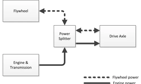
Concept. The architecture of hybrid system is shown in Fig. 1. The arrows represent the power flow. It is using the parallel hybrid system [3]. Engine post as the main power supply, while flywheel as secondary. It seems like the vehicle will do the selection which power systems to use, in fact in this model, no selection is happen. Vehicle will run as normal operation using engine. The
reduction on engine’s power contribution is happen when charge flywheel is connected to the drive
axle mechanically through clutch system automatically. The portion of the engine power is covered by the flywheel power. Therefore, the energy conservation is happens whereas flywheel is in operation. The advantage is the driver feel like driving a normal vehicle without noticing the interchange between engine and flywheel.
Flywheel
Engine & Transmission
Power
Splitter Drive Axle
Flywheel power Engine power
Fig. 1: The main components of flywheel hybrid vehicle.
Driving Phase. The driving phase can be divided into three major phase as shown in Fig. 2 below.
In the first two phase, the vehicle is propel forward using power from either engine or flywheel. During this time, efficiency of the engine is investigated and compared with conventional motorcycle. The last phase is the most crucial phase for flywheel. This is because, during this phase period, the flywheel power is charged through the regenerative braking process (or regenerative deceleration) [5].
Ideal Power Mode. The governing equations for this system are derived using Newtonian
Fig. 2: Three major phases of driving strategies. Fig. 3: Free body diagram of motorcycle.
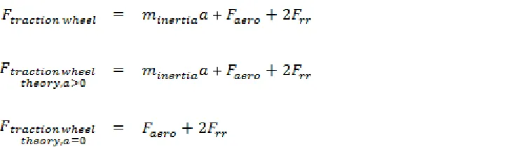
Theoretically, general traction force is equal to addition of inertia force ( and road load as shown in Eq. 1. Road load consists of aerodynamic drag and front and rear wheel rolling resistance. In this case, gradient load is not included because vehicle is moving on planar surface. However, theoretical value for traction force in acceleration phase and steady speed phase is slightly different. For the first phase, the traction force is similar to the general traction force as shown in Eq. 2 below. In the second phase, inertia force is zero due to zero acceleration. Therefore, the traction force during steady speed is equal to road load only as shown in Eq. 3.
+ (1)
+ (2)
(3)
Model-based Power Mode. Theoritical value of traction force in first and second phase is slightly
different. However, in model-based traction force, there is no different in equation for both phases as shown in Eq. 4 below. This equation is valid for both case of driving phase since this equation related to engine power.
(4)
Power Transfer Efficiency (PTE). The final outcomes of this research are to investigate the efficiency of power supply during various conditions of acceleration phase and steady speed phase. The PTE is the ratio of measured vehicle power with ideal vehicle power as in Eq. 5 and 6. Eq. 5 is the PTE of vehicle during acceleration phase while Eq. 6 is the PTE of vehicle during steady speed phase. Both equations fit both type of motorcycles. In this research, since back tracing simulation is used; therefore the vehicle power means here is the traction power at wheel. In this research, efficiency that more than 100% means vehicle received more power than required. Lower the value, better the PTE performance of the power supply.
(6)
Motorcycle Simulation
Mechanism of Hybrid Motorcycle. Driving phase can be divided into three which are acceleration
phase (0-100kph, 0-100sec), constant velocity phase (100kph, 50sec) and deceleration phase (100-0kph, 100sec). This driving pattern will be repeated again to show the phase where the flywheel is functions as a second power source. Data explained is referred to the graph below.
50 100 150 200 250 300 350 400 450 500
Kiraan Kuasa Tarikan Pada Roda - Pengiraan (Biru) & Sebenar (Merah)(W)
Masa Simulasi (s)
4 Motor Hibrid - Kuasa Roda Tenaga (W)
Masa Simulasi (s)
Fig. 4: Flywheel hybrid mechanisms (a) Mix velocity (kph) (b) Power traction wheel (W) ideal (blue) and model (red) (c) Power of engine (W) (d) Power of Flywheel (W)
During the first phase of acceleration (0-100secs), main transmission will be connected to the the engine. Engine will supply power to the wheel through the main transmission and the motorcycle will accelerate until constant speed is attained at 100kph. Engine will be in constant mode where constant power is supply to maintain the constant velocity (100-150secs). After 150secs, motorcycle will decelerate until it fully stops at 250secs. During this phase (deceleration, 150-250secs), main transmission is connected to the flywheel. Torque from the wheel will be transferred to the flywheel then it will rotate the flywheel. After the motorcycle is stop, the main transmission is disengaged from the flywheel, and then flywheel is rotating freely. Motorcycle will be slow down and friction brake is applied to make a full stop. This reverse action is call regenerative braking mode. By now, the flywheel is fully charge and has internal storage energy to propel the motorcycle.
When the motorcycle decides to move again (250-350secs), the hybrid mode will be activated. Main transmission now is connected back to the flywheel [5]. Therefore, the stored internal energy will transferred back to the wheel in a rotary action. Literally, flywheel will rotate the wheel until it loses all it stored energy. Motorcycle will propel forward. After that, engine will take over the flywheel to supply power to the wheel. From Fig. 4(d), at 250-300 seconds, power capacity of the flywheel is decreased. That’s mean the flywheel is transferring power to the wheel. When reach 300 seconds, all internal storage power of the flywheel have been depleted. Hence, the engine is fire up and continues to supply power as in Fig. 4(c).
(a)Motorcycle velocity (kph) vs. Time (sec)
(b)Power traction wheel (W) ideal (blue) and model (red) vs. Time (sec)
(c)Power of engine (W) vs. Time (sec)
Result and Discussion
Maximum Power Comparison between Engine & Flywheel. The power source consists of
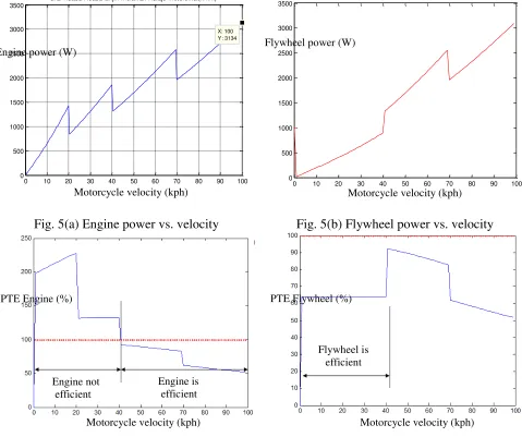
internal combustion engine and flywheel. Both components are either working alone such in the conventional motorcycle or are working together such in the hybrid motorcycle. Fig. 5(a) shows the power produce by the engine base on specific velocity. The tooth shape on this graph is a phase where gear shift happen. Base on the four gear transmission model, the gear shift happen at velocity of 20kph, 40kph and 70kph. The maximum power produce at 100kph is 3134W. Fig. 5(b) shows the relationship between the flywheel powers versus the motorcycle velocity. From this figure, flywheel is capable to store up to 3091W maximum kinetic energy which nearly similar to the maximum power produces by internal combustion engine. Therefore, the flywheel is capable to working alone in propelling the motorcycle.
Halaju Motorsikal(km/h) 0 10 20 30 40 50 60 70 80 90 100
0
Fig. 5(a) Engine power vs. velocity Fig. 5(b) Flywheel power vs. velocity
Fig. 6(a) PTE Engine vs. velocity Fig.6(b) PTE Flywheel vs. velocity
PTE of Engine & Flywheel. From the simulation of conventional and hybrid motorcycle, the internal combustion engine and the flywheel have different efficiency at the same velocity. 100% line is the PTE cutoff line where value below it show energy conservation while value above it show the waste in energy used. From Fig. 6(a), the velocity is between 1kph and 41kph, engine is over-supply power to the wheel which causes the power waste in this velocity range. Engine is supply up to 140% of power more than needed by wheel. Therefore, more efficient power source is needed to replace the engine. Hence, the flywheel is used to supply power during velocity range of 1kph to 41kph. Focus area is in velocity range of 1kph to 41kph where engine have difficulty in
Engine power (W) Flywheel power (W)
Motorcycle velocity (kph) Motorcycle velocity (kph)
Motorcycle velocity (kph) Motorcycle velocity (kph)
supply optimal power to the wheel. From Fig. 6(b), it is clearly seen that the flywheel can supply power to the wheel more efficient at average PTE of 64%. Even though, at velocity more than 41kph, flywheel is still capable to supply power to the wheel in less than 100% PTE. This graph show that the flywheel is capable to replace engine at velocity below 41kph to increase overall power transfer efficiency.
Conclusion
From this research, the result shows that the flywheel is supply less power than needed by the wheel. Literally, flywheel is used less power to propel the motorcycle because the PTE is less than 100%. That means the power supply by the flywheel is less than ideal power needed by the motorcycle to propel. The ideal power traction is use as a base data for comparison of both systems in transfer power to the wheel. In this case, systems which have lowest PTE are the most efficient powertrain system. Mathematical model of the power transfer efficiency (PTE) for the flywheel hybrid motorcycle is successfully developed. This model proved the function of flywheel as an alternative power source which can increase the PTE from the power source to the wheel. The overall power consumption of the motorcycle can be optimizing with power conservation of 36%. If a conventional motorcycle uses the total of 1000W of power for specific driving cycle, the hybrid motorcycle is use only 640W of total energy with energy conservation of 360W per driving cycle.
Acknowledgement
The authors would like to acknowledge Universiti Teknikal Malaysia Melaka (UTeM) under Short Term Grant Scheme (PJP/2012/FKM(17C)/S01109) and Ministry of Higher Education (MOHE) for supporting and funding this research activity.
References
[1] Information on Kementerian Pengangkutan Malaysia, “ Jadual 1.2: Jumlah Terkumpul
Kenderaan Bermotor Mengikut Jenis dan Negeri di Malaysia, Sehingga 30 September 2012”,
http://www.mot.gov.my/my/Statistics/Pages/Land.aspx, retrieve on 21 February 2013.
[2] Information on Carbon Footprint Ltd, “Motorbike Carbon Footprint Calculator”, http://calculator.carbonfootprint.com/calculator.aspx?tab=5, retrieve on 20 February 2013.
[3] Saurabh Mahapatra, Tom egel, Raahul Hassan, Rohit Shenoy, Micheal Carone, "Model-Based Design for Hybrid Electric Vehicle Systems", The Mathworks Inc, 2008.
[4] Jeongwoo Lee, "Vehicle Inertia Impact on Fuel Consumption of Conventional and Hybrid Electric Vehicles Using Acceleration and Coast Driving Strategy", PhD Thesis, Virginia Polythechnic Institute and State University, 2009.
[5] Muhammad Zaidan Abdul Manaf, “Pemodelan Motosikal Hibrid Roda Tenaga Untuk
Mengoptimumkan Penggunaan Tenaga”, Laporan Sarjana Kejuruteraan Mekanik, Universiti
Kebangsaan Malaysia, 2012
[6] Reza N. Jazar, “Vehicle Dynamics:Theory and Application”, Springer, 2009
[7] Gustaf Lagunoff, "Automotive Hybrid Technology: Status, Function and Development Tools", Master Thesis, Lulea University of Technology, 2008.