Computational Simulation of Boil-Off Gas Formation inside Liquefied
Natural Gas tank using Evaporation Model in ANSYS Fluent
Mohamad Shukri Zakaria
1,a,
Kahar Osman
2,b, Mohd Noor Asril Saadun
1,c,
Muhammad Zaidan Abd Manaf
1,d, and Mohd Hafidzal Mohd Hanafi
1,e1
Faculty of Mechanical Engineering, Universiti Teknikal Malaysia Melaka, 76100 Durian Tunggal, Melaka, Malaysia
2
Faculty of Mechanical Engineering, Universiti Teknologi Malaysia, 81310 Skudai, Johor, Malaysia
a formation, venting and flared the Boil-off gas (BOG) considered as one of the contribution to the Greenhouse Gas (GHG) emission nowadays. The current model or method appearing in the literature is unable to analyze the real behavior of the vapor inside Liquefied Natural Gas (LNG) tank and unable to accurately estimate the amount of boil-off gas formation. In this paper, evaporation model is used to estimate LNG Boil-Off rate (BOR) inside LNG tank. Using User Define Function (UDF) hooked to the software ANSYS Fluent. The application enable drag law and alternative heat transfer coefficient to be included. Three dimensional membrane type LNG cargos are simulated with selected boundary condition located in the United States Gulf Coast based on average weather conditions. The result shows that the value of BOR agrees well with the previous study done with another model and with International Marine organization (IMO) standard which is less than 0.15% weight per day. The results also enable us to visualize the LNG evaporation behaviors inside LNG tanks.
Introduction
Saturated boiling temperature of LNG is known to be -163oC. From liquid state of LNG, the gas state which is Natural Gas was produced during marine transportation due to continuous heat flow through the LNG tank wall. Movement of the gaseous inside the tank can be illustrated using Computational Fluid Dynamics software which had unable to be utilizing if only amount of heat flow are considered. Excess of the vapor then need to be removed to avoid pressure build up inside the LNG tank. The removed gaseous from the tank will bring out economic and social impact to the environment.
In this paper, the right choice of the multiphase boiling model together with drag law and particle size will be able to predict the behavior movement of the vapor phase. Thus, the detail understanding of vapor formation location enable researchers and engineers to minimize the boil off gas loses.
Modeling
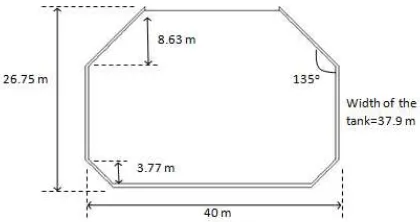
Geometry. LNG membrane type tanker is used in this paper for analysis purpose since its cover more than half of total LNG tanker used around the world [1].The two dimensional geometry of the tank in this paper is refer to the work done by [2] are shown in Figure 1. The width of the tank was determined by the author in order to fill the requirement of the analysis and for validation purpose. Three dimensional geometry was constructed using software GAMBIT and meshed using tetrahedral element. All side of the tank except the upper side taken as wall properties boundary condition with specific value for boundary condition according to the real industry practice. While
the upper side of tank set with pressure outlet boundary condition to enable liquid and vapor exit or backflow depends on the corresponding pressure at the outlet. In this case, it is assume that the outlet pressure is 101.3 kPa in lieu with the real operation pressure of LNG whereas slightly higher than atmospheric pressure [3].
Fig. 1: Illustration of the tank in 2-Dimensional
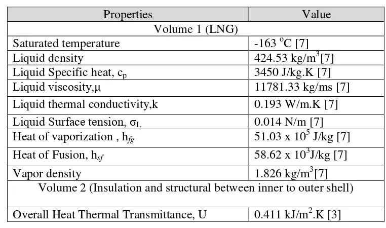
Material Properties. Two volumes are defined in the model. There is structural volume covers from outer shell to the inner shell of the tank expose to the cargo, which is represent material of main insulation, outer steel, inner steel ,area of support junction, aggregate with different size, angle iron, ballast medium and so on. The other one is cargo volume represents the material of LNG. The related of the material properties used for each volume are shown in Table 1.
BOR Formula. The key parameters in determining the BOG formation are density and enthalpy of the LNG. Several model and equation appearing in literature [4,5] is to estimate the density of the natural gas vapor. They used Benedict-Webb-Rubin (BWR) equation to estimate natural gas density inside storage tank. BOR was computed using well known energy balance equation [6]
(1)
The equation shows that the BOR are directly related to the variation of heat leakage, q, heat of vaporization hfg , LNG density and total LNG volume inside the tank. However, in this paper, LNG
BOG formation was determined purely based on saturated temperature of LNG (-163oC).
(2)
Where r is under relaxation factor, VFl is Liquid volume fraction, ρl is Liquid density, Tl is Liquid
temperature and Tsatis saturated temperature.
The implementation of UDF in ANSYS FLUENT enable to use fundamental equation of fluid flow. The schiller-naumann drag law use for the phase interaction which was used to describe the drag between the spherical vapor particle and surrounding LNG liquid condition.
.
% 100 3600
24x x
x Vh
q BOR
fg
Table 1: Material properties used in the analysis
Properties Value
Volume 1 (LNG)
Saturated temperature -163 oC [7]
Liquid density 424.53 kg/m3[7]
Liquid Specific heat, cp 3450 J/kg.K [7]
Liquid viscosity,µ 11781.33 kg/ms [7] Liquid thermal conductivity,k 0.193 W/m.K [7] Liquid Surface tension, σL 0.014 N/m [7]
Heat of vaporization , hfg 51.03 x 10⁵ J/kg [7]
Heat of Fusion, hsf 58.62 x 10³J/kg [7]
Vapor density 1.826 kg/m3[7]
Volume 2 (Insulation and structural between inner to outer shell)
Overall Heat Thermal Transmittance, U 0.411 kJ/m2.K [3]
Assumptions of the Model. Several simplifying assumption were made in order to meet the model requirement, while at the same time preserving the accuracy and reliability of computed BOG mass flow.
1) Vapor temperature is at saturated condition, so that the relation of vapor –liquid is known at equilibrium condition.
2) The boiling phase is on nucleate boiling regime.
3) Any backflow condition occurred at the surface consider as in liquid phase
Validation
The model was validated by comparing the result from simulation done by [3]. Software used by [3] is Aspen HYSYS 2004.2 to simulate various conditions for completing trip of LNG. There are several parameters used in this study and by [3] are slightly different in order to prove that the simplified model and assumption are applicable to the benchmark result done by [3]. Table 2 shows the comparison on simulation parameter generally used by this study and by [3] for validation purpose.
Table 2: Comparison parameters use for validation purpose
The analysis done based on single independent scenario as follows. For the Overall heat transmittance, we assumed the value is 0.411kJ/m2.K which is corresponding to insulating material of polyurethane foam and ratio of support junction connecting inner and outer shell of the tank [3]. The capacity of the single tank was assume to be 35062 m3 and had been use in a real practice for 145000 m3 ship size. The cofferdam area which is in between the tanks inside LNG ship was taken as 5oC in order to satisfy minimum allowable design temperature of the shell structure material. The ambient temperature are based on critical condition accordance with relevant requirement on the United Stated Cost Guard (USCG) which is 45oC and 32oC for air and seawater temperature, respectively. The ambient air and seawater are separated by the draft of the typical LNG carrier which is around 10 meter [5].
Evaporation Model
In order to use equation (2), properties of each cell which are liquid density, liquid volume fraction and liquid temperature are required. For example the total liquid volume fraction of the LNG inside LNG tank during boil-off formation can be obtained by intergrating from the whole volume of the tank.
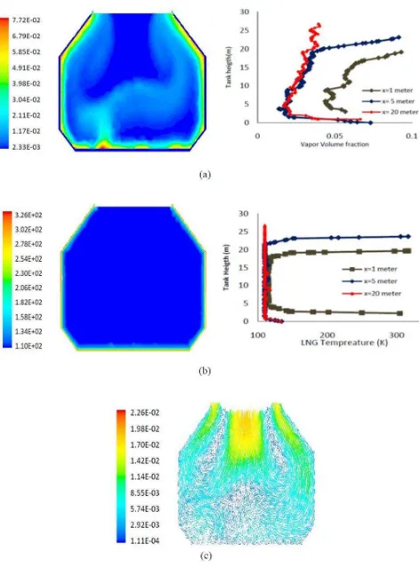
It can be seen that from Fig.4(a) the relation between LNG temperature and vapor formation. As expected, vapor formations are larger near the wall of the LNG tank due to higher LNG temperature at the corresponding location. Due to lighter density of vapor compare to LNG, the vapor will buoyancy and tend to exit the surface. However, the backflow occur at the surface due to pressure acting at the outlet at the saturated condition. Only vapor pressure which is higher than zero gauge pressure setup at the pressure outlet will escape and Boil-Off considered loose.
As the heat leakage through the structural and insulation part of the tank are continuous, the LNG temperature are still maintain around the saturated temperature. This statement can be shown in Fig. 4(b). The temperature of LNG became slightly higher than saturated temperature only near the wall. As the LNG far from the wall, the LNG temperature still maintain at the saturated temperature. This is importance and aim for LNG transportation mode for releasing boil-off gas in order to maintained LNG in liquid phase as much as possible.
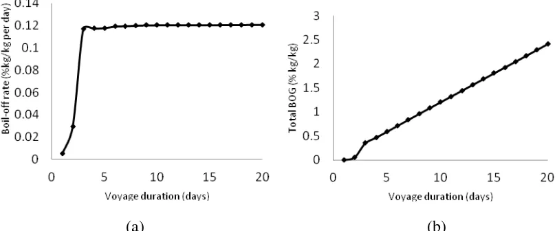
Also can be seen from graph presented in Fig. 3, the value of BOR become almost constant after approximately 5 days after voyage for the corresponding boundary condition.This happen due to initial LNG temperature of LNG are set slightly below saturated temperature. This phenomenan also due to performance of the LNG tank insulation. Higher thermal conductance of insulation expected to give more time for BOR a constant reading .
(a) (b)
Fig. 4: Contour and profile of (a) vapor volume fraction (b) vapor temperature and (c) velocity magnitude for Air Temperature =318K, Seawater Temp=305K, U=0.411 at centre of the tank
Conclusion
The use of CFD code in ANSYS Fluent can be utilized in modeling the vapor behavior of LNG inside tank. However, the right and correct use of the model is very important in simulation the model. Improper modeling method is not able to track the movement of gas phase inside the tank.
The develop model can be used to predict behavior of LNG vapor inside the tank, thus to capture the LNG losses and reduce the energy waste and gas emission. The model also able to get the BOR for specific boundary condition valued 0.11 % per day which below standard industry range and within specification of IMO standard.
Acknowledgement
The authors would like to acknowledge UniversitiTeknikal Malaysia Melaka (UTeM) PJP/2012/FKM(12A)/S01087 and Universiti Teknologi Malaysia (UTM) through Flagship Research Grant for supporting and funding these research activities
References
[1] Javier Romero and Ignacio Mosquera: Maritime Transportation and Exploitation of Ocean and Coastal Resources. Proceedings of the 11th International Congress of the International Maritime Association of the Mediterranean. Vol.2 (2005), p. 883-892
[2] Chen, H. C.: CFD Simulation of Compressible Two Phase Sloshing Flow in a LNG Tank. Ocean System Engineering. Vol.1 (2011), p. 31-57.
[3] Hasan, M. Zheng, M.A. Karimi, I.A.: Minimizing Boil-Off Losses in Liquefied Natural Gas Transportation. Industrial & Engineering Chemistry Research. Vol. 48(21) (2009), p. 9571-9580.
[4] Q. S.Chen ,J. Wegrzyn , and V. Prasad: Analysis of temperature and pressure changes in liquefied natural gas cryogenic tanks. Cyrogenic. Vol. 44(10) (2004), p. 701-709.
[5] Adom, E. Islam, S. Z. Ji, X.: Modelling of Boil-Off Gas in LNG Tanks A Case study. International Journal of Engineering and Technology, Vol. 2 (4) (2010) p.292-296
[6] Mohamad Shukri Zakaria, Kahar Osman, and Md. Nor Musa: Boil-Off Gas Formation inside Large Scale Liquefied Natural Gas (LNG) Tank Based on Specific Parameters. Applied mechanics and Material Vol. 229-231 (2012), p. 690-694
[7] Guyer. E. C. and Brownell, D. E: Handbook of Applied Design. (reprinted ed.): Taylor &Francis. (1999)