DOI: 10.12928/TELKOMNIKA.v15i2.6325 549
Editorial
Performance Evaluation of Cascaded Multilevel
STATCOM using Hardware-in-the-Loop (HiL) Test
based on Real-Time Digital Simulator (RTDS)
Lihua Li1, Lin Xu2, Yang Han*3 1
JinCheng College of Sichuan University, No.1, Xiyuan Avenue, West Chengdu High-Tech Zone, Chengdu 611731, China
2
State Grid Sichuan Electric Power Research Institute, No.24, Qinghua Road, Chengdu 610072, China
3
University of Electronic Science and Technology of China, No.2006, Xiyuan Avenue, West Chengdu High-Tech Zone, Chengdu 611731, China
*Corresponding author, e-mail: [email protected]
Abstract
The cascaded H-bridge multilevel converter topology has been increasingly utilized for reactive power compensation purposes for the medium voltage distribution systems. The static synchronous compensators (STATCOMs) or static var generators (SVGs), are difficult to be tested in the field due to the unpredicted network operation conditons. This paper presents an effective method to test the STATCOM/SVG controllers based on the real-time digital simulator (RTDS), which has the benefit of easy implementation, low cost, online parameter tuning and high efficiency. The experimental results of STATCOM/SVG under steady state and dynamic conditions are presented to verify the proposed approach, which can be widely applied in other grid-interfaced power electronic converters and smart grid applications.
Keywords: static synchronous compensator,STATCOM,SVG, hardware-in-the-loop,RTDS
Copyright © 2017 Universitas Ahmad Dahlan. All rights reserved.
The power quality monitoring and conditioning has been widely applied to the electric power systems, in order to regulate the voltage and reactive power at the point of common coupling (PCC) [1-3]. In retrospect, the passive compensators, such as the LC filters, were adopted duo to low cost. However, the LC-filter based passive compensation approach may introduce resonance, harmonic current amplification problems, which are detrimental for the stable operation of the electric power systems. The voltage source converter (VSC)-based dynamic reactive power compensators, i.e., STATCOM or SVG, have been recognized as the most effective way to regulate the grid voltage and improve power quality [4-6].
Recently, the cascaded H-bridge multilevel converter topology has been increasingly utilized for the reactive power compensation purposes for the medium voltage distribution systems. The static synchronous compensators (STATCOMs) or static var generators (SVGs), are difficult to be tested in the field due to the unpredicted network operation conditons. This paper presents an effective method to test the STATCOM/SVG controllers based on the real-time digital simulator (RTDS), which has the benefit of easy implementation, low cost, online parameter tuning and high efficiency [7-10].
connected in series and coupled to the grid by the interfacing inductor Lu, Lv, Lw. Thus multilevel output voltage can be synthesized at the ac terminal of the multilevel converter.
In order to achieve the purpose of grid voltage at the point of common coupling, and dynamic reactive power regulation, the dc-link capacitor voltage control and output current control of the STATCOM/SVG are crucial important. Without the stable operation of the dc-link capacitors, the whole system of the STATCOM/SVG would be destabilized in the field.
Figure 1. Circuit diagram of cascaded H-bridge multilevel STATCOM/SVG
Figure 2 shows the control diagram of the cascaded H-bridge multilevel STATCOM, which consists of active power decoupling controller, the three-phase grid voltage controller, and the dc-link capacitor voltage controller across the individual inverter modules. In Figure 2, p* and q* indicates the set point of the active and reactive powers of the STATCOM/SVG, Vdc* indicates the set point of the dc-link capacitor voltages, and iu, iv, iw denotes the output currents of STATCOM/SVG. The synthesized modulation signals of the STATCOM/SVG are denoted as uun*, uvn* and uwn*, respectively.
Figure 2. Control diagram of the cascaded H-bridge multilevel STATCOM
u
Total Active Power Control Dc-link Capacitor Voltage Balancing
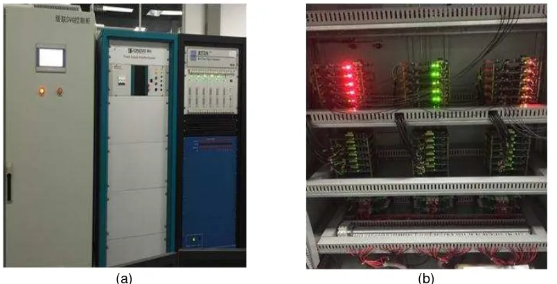
Figure 3 shows the photo of the expermental setup using the RTDS platform. Figure 3(a) shows the cascaded H-bridge multilevel STATCOM/SVG, and Figure 3(b) shows the detailed view of the multilevel STATCOM/SVG hardware platform. The control signals of the IGBTs of each H-bridge inverter modules are interfaced with the RTDS using optical fibers, and the analog signals generated by the inverter modules are connected with RTDS using operational amplifiers to establish a closed-loop experimental system.
Figure 4 shows the experimental results when the multilevel STATCOM/SVG generates a constant reactive power of 6MVar. Figure 4 (a) shows the individual dc-link capacitor voltages across each phase leg. Figure 4 (b) shows the output current and multilevel voltage of the STATCOM/SVG. Figure 5 shows the experimental results when the multilevel STATCOM/SVG absorbs a constant reactive power of 6MVar. Figure 5 (a) shows the individual dc-link capacitor voltages across each phase leg. Figure 5(b) shows the output current and multilevel voltage of the STATCOM/SVG.
(a) (b)
Figure 3. Photo of the expermental Setup using the RTDS platform. (a) The cascaded H-bridge multilevel STATCOM/SVG; (b) The detailed view of the multilevel STATCOM/SVG
(a) (b)
Figure 4. The experimental results when the multilevel STATCOM/SVG generates a constant reactive power of 6MVar. (a) The individual dc-link capacitor voltages across each phase leg;
(a) (b)
Figure 5. The experimental results when the multilevel STATCOM/SVG absorbs a constant reactive power of 6MVar. (a) The individual dc-link capacitor voltages across each phase leg;
(b) The output current and multilevel voltage of the STATCOM/SVG.
(a) (b)
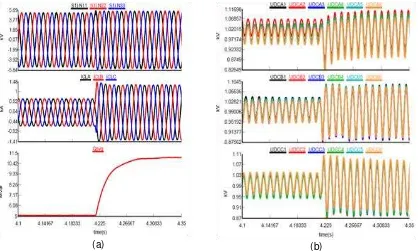
Figure 6. The dynamic response of the multilevel STATCOM/SVG under the transient increase of reactive power from 5Mvar to 10MVar. (a) The gird voltages, the output currents of the STATCOM/SVG, and the instantaneous reactive power; (b) The individual dc-link capacitor
voltages across each phase leg
capacitor voltages across each phase leg. The stability of the closed-loop control system is ensured under abrupt reactive power variations, which justifies the effectiveness of the control scheme.
The presented RTDS-based real-time simulation method provides helpful solution for the closed-loop controller test for the power electronic converters, which can be easily extended to other grid-connected converters, renewable energy systems and smart grid applications.
References
[1] P Kundur, Power System Stability and Control. New York: Mc-Graw-Hill, 1994.
[2] N Mohan, TM Undeland, WP Robbins. Power Electronics: Converters, Applications, and Design. New York: Wiley. 1995.
[3] M Ilic, J Zaborszky. Dynamics and control of large electric power systems. New York: Wiley, 2000. [4] R Marconato. Electric Power Systems. Milan, Italy: CEI, 2008; 2.
[5] A Sharma, SC Srivastava, S Chakrabarti. Testing and validation of power system dynamic state estimators using real time digital simulator (RTDS). IEEE Transactions on Power Systems. 2016; 31(3): 2338-2347.
[6] M Park, I Yu. A novel real-time simulation technique of photovoltaic generation systems using RTDS,
IEEE Transactions on Energy Conversion. 2004; 19(1): 164-169.
[7] A Nikander. Development and testing of new equipment for faulty phase earthing applying RTDS.
IEEE Transactions on Power Delivery. 99. DOI:10.1109/TPWRD.2015.2505779.
[8] SM Baek, JW Park. Nonlinear parameter optimization of FACTS controller via real-time digital simulator. IEEE Transactions on Industry Applications. 2013; 49(5): 2271-2278.
[9] Z Xu, D Jianyong, L Mei, Z Shuang, Z Ni, Z Ruoxi, Z Buhan, M Chengxiong. Using STATCOM with energy storage to enhance AC-DC system stability. Telkomnika. 2016; 14(2): 423-430.