SMALL SCALE INTELLIGENT VEHICLES
IAN DIVINE HILLARY BAJAU
This report is submitted to Faculty of Mechanical Engineering,
In partial fulfillment for Bachelor of Mechanical Engineering (Automotive)
Faculty of Mechanical Engineering Universiti Teknikal Malaysia Melaka
“Saya/Kami akui bahawa telah membaca karya ini dan pada pandangan saya/kami karya ini
adalah memadai dari segi skop dan kualiti untuk penganugerahan Ijazah Sarjana Muda Kejuruteraan Mekanikal (Automotif)”
Tandatangan : ………
Nama Penyelia 1 : ..………..
Tarikh : ………
Tandatangan : ………
Nama Penyelia 2 : ..………..
i “Saya akui laporan ini adalah hasil kerja saya sendiri kecuali ringkasan dan petikan yang
tiap-tiap satunya saya telah jelaskan sumber”
Tandatangan : ………...………
Nama Penulis : IAN DIVINE HILLARY BAJAU
iii ACKNOWLEDGEMENT
This project could not have been finished without Mr. Herdy Rusnandi who not only served as my supervisor but also encouraged and challenged me throughout my Projek Sarjana Muda (PSM). He patiently guided me through the project process, never accepting less than my best efforts. I would like thank him whole-heartedly.
I would like to thank my family who support me either in motivations or financially. Thanks to all my friends who help me throughout my PSM. Without them, this project may never have finish with flying colors. Thanks also to Claudia Uray Sabestian, who is my reason for trying to be the best that I can be, and who lights my way when it becomes dark.
ABSTRACT
Intelligent Vehicle (IV) is one of the technology that improving capabilities of a modern vehicles. Advanced sensing, communications, and computing promise to allow vehicles to operate automatically, to avoid collisions, and to prevent or deal with injuries when a crash does occur. Recently, there has been an increase in the practical application of ACC (adaptive cruise control), which measure the following distance to the preceding vehicle by radar and automatically maintain an appropriate following distance, and Lane Recognition systems, which recognize lane using vision sensors and keep the vehicle from deviating from the lane. Current systems are based on the premise of highway driving, but in the future, these systems will come to be used on regular roads as well, in pursuit of even greater safety and comfort. Just for this, this project will simulate the IV technology into a small scale IV model to understand more about the Intelligent Vehicle.
v ABSTRAK
TABLE OF CONTENTS
CHAPTER CONTENT PAGE
ADMISSION i
DEDICATIONS ii
ACKNOWLEDGEMENT iii
ABSTRACT iv
ABSTRAK v
TABLE OF CONTENTS vi
LIST OF TABLES viii
LIST OF FIGURES ix
LIST OF SYMBOLS xi
LIST OF ATTACHMENT xii
CHAP. I INTRODUCTION 1
1.1 Project background 1
1.2 Objective 3
1.3 Scope 3
1.4 Problem Statement 4
CHAP.II LITERATURE 5
2.1 Intelligent Vehicles (IV) : Adaptive Cruise Control 5
vii
CHAPTER CONTENT PAGE
2.3 Digital Processor Platform 8
2.4 PIC Processor Platform 11
2.5 Model Vehicle Platform 14
2.6 Infrared Sensor Arrays 17
2.7 Hall Effect Sensor Arrays 18
2.8 Visual System 20
2.9 Ultrasonic Sensors 22
2.10 Microcontroller - Application in Automotive 23
CHAP III METHODOLOGY 25
3.1 Mathematical Modeling 27
3.1.1 Kinematic Model 27
3.1.2 Headway Controller Algorithm Development 32
CHAP IV RESULT 35
4.1 MATLAB Simulation Result 35
CHAP V DISCUSSION 59
5.1 Application Of The First Order Control Law 59 5.2 Application Of The Sliding Mode Control Law 62
CHAP VI SUMMARY 64
6.1 Conclusion 64
6.2 Future Work 66
REFERENCE 68
LIST OF TABLES
NO TITLE PAGE
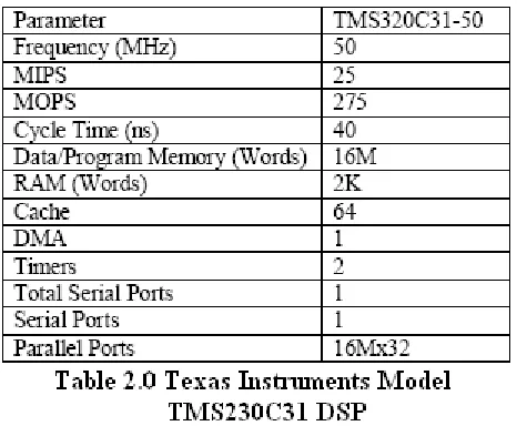
2.0 Texas Instruments Model TMS230C31 DSP 8
2.1 Signal Characteristic for the HAL506UA-E 19
Hall Effect Sensor.
ix LIST OF FIGURES
NO TITLE PAGE
2.0 Block Diagram of a cruise control system 6 2.1 High-level architecture block diagram of the vehicle 7
hardware platform
2.2 Microchip PIC Processor Pin Diagram 11
2.3 Encoder specifications 13
2.4 PWM control signal format for steering and velocity 15 2.5 Example of Infrared Control Circuit Schematic 17 2.6 Example of Infrared Control Circuit Schematic 18
2.7 Camera processing block diagram 21
2.8 Block Diagram for the Ultrasonic Module 22
3.0 Research Methodology 26
3.1 (a) Point-to-point stabilization 28
(b)Path following 28
3.2 Generalized coordinates of a car-like robot 28 3.3 Coordinate definition for a path following task 29 4.1 Leader velocity input and transformed velocity 36
with headway of 0.5m
4.2 Leader velocity input and transformed velocity 36 with headway of 0.5m
4.3 Error in headway distance with headway of 0.5m 37 4.4 Headway distance between two vehicles with 37
NO TITLE PAGE 4.5 Leader velocity input and transformed velocity 39
with headway of 0.9m
4.6 Follower velocity input and transformed velocity 39 with headway of 0.9m
4.7 Error in headway distance with headway of 0.9m 40 4.8 Headway distance between two vehicles with 40
headway of 0.9m
4.9 Leader velocity input and transformed velocity 41 with headway of 0.9m
4.10 Follower velocity input and transformed velocity 42 with headway of 0.9m
4.11 Error in headway distance with headway of 0.9m 42 4.12 Headway distance between two vehicles with 43
headway of 0.9m
4.13 Leader velocity input and transformed velocity 44 with headway of 0.5m
4.14 Follower velocity input and transformed velocity 45 with headway of 0.5m
4.15 Error in headway distance with headway of 0.5m 45 4.16 Headway distance between two vehicles with 46
headway of 0.5m
4.17 Leader velocity input and transformed velocity 48 with headway of 0.9m
4.18 Follower velocity input and transformed velocity 48 with headway of 0.9m
4.19 Error in headway distance with headway of 0.9m 49 4.20 Headway distance between two vehicles with 50
headway of 0.9m
xi
NO TITLE PAGE
4.24 Headway distance between two vehicles with 53 headway of 0.5m
4.25 Leader velocity input and transformed velocity 54 with headway of 0.5m
4.26 Follower velocity input and transformed velocity 55 with headway of 0.5m
4.27 Error in headway distance with headway of 0.5m 55 4.28 Headway distance between two vehicles with 56
headway of 0.5m
4.29 Leader velocity input and transformed velocity 57 with headway of 0.5m
4.30 Follower velocity input and transformed velocity 57 with headway of 0.5m
4.31 Error in headway distance with headway of 0.5m 58 4.32 Headway distance between two vehicles with 58
LIST OF SYMBOLS
l = length of the car body
è = orientation of the vehicle x-axis ö = angle of the front wheels
h
e = headway error
h = headway distance
ù(t) = estimated velocity of the lead vehicle in terms of arc length at the current sample time
f(c) = dynamics of the follower v1 = driving velocity
ˆ( )t
xiii LIST OF ATTACHMENT
NO TITLE PAGE
1 Matlab simulation source code -
2 Project Planning PSM1 -
3 Project Planning PSM2 -
4 HW 1 Cruise Model -
CHAPTER I
INTRODUCTION
In order to complete the Bachelor in Mechanical Engineering in Automotive, student required to implement a final year project (Projek Sarjana Muda, PSM). My project title is “Small Scale Intelligent Vehicles” which is I have to develop a simulation of a small scale intelligent vehicle as a scale model platform. Small scale Intelligent Vehicle also called Robotic Car. This project will refer to the robotic car of Flexible Low-cost Automated Scaled Highway (FLASH) project for its hardware platforms as there will no fabricating of the small scale in this project.
1.1 Project Background
2 Adaptive cruise control allows a user to input a desired vehicle velocity, the same way one would set cruise control in a modern vehicle. Adaptive cruise control also allows the driver to set a desired following distance for objects that may be in front of the vehicle. As long as the adaptive cruise control system does not detect any obstacles in the vehicle’s path, the maximum velocity as entered by the driver will be maintained.
When an object is in the vehicle’s path, the adaptive cruise control system will adjust the vehicle’s velocity accordingly to maintain the desired, safe, distance from the obstacle. It is easy to see how adaptive cruise control can be further enhanced to provide lane changing mechanisms for automatic passing of slower traffic, and to provide collision avoidance mechanisms that allow vehicles to not only maintain a specific distance, but to go around, or even halt in the presence of an accident or other nonmoving obstacle in the road.
Development of control systems for scaled, as well as full sized, vehicles should be concerned at all times with the safety of the vehicle’s occupants, and with the stability of the system as a whole. Automatic headway control allows a driver another degree of freedom in controlling a vehicle as mentioned earlier.
1.2 Objective
The objective of this project is to develop a simulation of a small scale intelligent vehicle as a scale model platform. By developing simulation in a small scale Intelligent Vehicle, we can simulate and understand how the electronic control system applied in automotive field.
1.3 Scope
The scopes of this project are stated as below:-
4 1.5 Problems statement
Consider some of the implications of cars are Intelligent Vehicle.
We might eliminate the more than ninety percent of traffic crashes that are caused by human errors such as misjudgments and inattention.
We might reduce antisocial driving behavior such as road rage, rubbernecking delays, and unsafe speeds, thereby significantly reducing the stress of driving.
The entire population, including the young, the old, and the infirm, might enjoy a higher level of mobility without requiring advanced driving skills.
The luxury of being chauffeured to your destination might be enjoyed by the general populace, not just the wealthiest individuals, so we might all do whatever we like, at work or leisure, while traveling in safety.
Fuel consumption and polluting emissions might be reduced by smoothing traffic flow and running vehicles close enough to each other to benefit from aerodynamic drafting.
Traffic-management decisions might be based on firm knowledge of vehicle responses to instructions, rather than on guesses about the choices that drivers might make.
CHAPTER II
LITERATURE REVIEW
2.1 Intelligent Vehicles (IV) : Adaptive Cruise Control
The mission of the IV is to accelerate the development and availability of advanced safety and information systems applied to all types of vehicles. Driver error is cited as the primary cause in about 90 percent of all police-reported crashes involving passenger vehicles, trucks, and buses; therefore, this is exactly where new technologies that allow the implementation of ideas like cruise control, adaptive cruise control, and platooning come into play. IV’s primary goal is to help drivers operate vehicles more safely and effectively with technologies integrated to create a fully intelligent vehicle that works cooperatively with the driver. IV advocates the creation of smart vehicles that fully consider the driver’s requirements, capabilities, and limitations.
6 When the driver approaches a vehicle in front of their own, he must decide whether to go around the obstacle, set the cruise control to match the speed of the blocking vehicle, or disengage the cruise control entirely.
In an effort to make cruise control more advanced, engineers and scientists posed the idea that forward looking system, like ultrasound, radar, and laser range finding technologies could be used to determine distance from vehicles and obstacles in front of the automobile, and then maintain a set distance from these obstacles.
Automatic headway control, also known as adaptive cruise control, is an area that has been under research for some time. Adaptive cruise control reduces driver strain by reducing the need to constantly monitor the vehicle’s speed. It can also be coupled with other driver convenience systems to provide control for lane changing, obstacle detection, and collision avoidance to further reduce driver fatigue when traveling long distances.
2.2 Hardware Environment
8 2.3 Digital Signal Processor Platform
The choice of a digital signal processor as the high level processor for the automated vehicle was made primarily for the ability to perform image processing. However, due to the inexpensive nature of today’s DSP platforms, the project was able to incorporate a DSP that could meet the project’s needs for image processing and that still had enough power to process the rest of the sensor data for the control of the vehicle. Table 2.0 lists the statistics for the Texas Instruments TMS320C31 DSP used by the FLASH project.
[image:23.612.189.422.262.454.2]treated as a slave device by the DSP, and once the sensor data has been processed and the appropriate drive commands have been determined, the commands are sent to the PIC processor, which is the direct interface to the system’s velocity and steering control.
Another feature of the DSP that the vehicle makes heavy use of is the boot loader capability. Upon resetting the vehicle, the processor is triggered by an external interrupt that indicates that the vehicle’s control code is loaded from one of three addresses in memory. In the case of the project vehicle, external interrupt 1, INT1, is de-asserted to indicate that the processor should begin loading code from address 0x400000. At this address resides an EEPROM that contains the operating program for the vehicle. The EEPROM is an ATMEL 24HC64B 8-bit wide memory device, and so the 32-bit DSP must read in the program code four bytes at a time, and reassemble by placing them correctly into one word in the internal RAM of the processor. Once the code has been reassembled in memory, the boot loader program transfers control of the processor to a pre-determined address, at which point the control code is executed.
Difficulties in converting the program to boot table format arose early in the development of the vehicle. While the control program could easily be compiled and loaded onto the DSP via a parallel interface with a host computer, the same code could not successfully be translated into a boot table and loaded from the EEPROM. As the code could be loaded and run from a host computer, the development of the EEPROM was tabled until such time as it was necessary to further the development of the vehicle.