UNIVERSITI TEKNIKAL MALAYSIA MELAKA
A Study On Calibration Technique Required For Optical Component
In Non-Contact Measuring System
This report submitted in accordance with requirements of the Universiti Teknikal Malaysia Melaka for the Bachelor Degree of Manufacturing Engineering
(Manufacturing Process) with Honors.
by
NOOR AMIN BIN SHAMSUDIN
FAKULTI KEJURUTERAAN PEMBUATAN
Rujukan Kami (Our Ref) : 13 Mei 2009
Rujukan Tuan (Your Ref):
Pustakawan
Perpustakaan Universiti Teknikal Malaysia Melaka (UTeM) Taman Tasik Utama, Hang Tuah Jaya,
Ayer Keroh, 75450, Melaka
Saudara,
PENGKELASAN LAPORAN PSM SEBAGAI SULIT/TERHAD
- LAPORAN PSM SARJANA MUDA KEJURUTERAAN PEMBUATAN (MANUFACTURING PEOCESS): Noor Amin Bin Shamsudin
TAJUK: A Study On Calibration Technique Required For Optical Component In Non-Contact Measuring System
Sukacita dimaklumkan bahawa tesis yang tersebut di atas bertajuk “A Study
On Calibration Technique Required For Optical Component In Non-Contact
Measuring System” mohon dikelaskan sebagai terhad untuk tempoh lima (5)
tahun dari tarikh surat ini memandangkan ia mempunyai nilai dan potensi
untuk dikomersialkan di masa hadapan.
Karung Berkunci 1200, Ayer Keroh, 75450 Melaka
DECLARATION
I hereby, declare this report entitled “A Study on Calibration Technique Required for Optical Component in Non-Contact Measuring System” is the results of my own research except as cited in the references.
Signature : ………
Author’s Name : ………
Date : ………
APPROVAL
This report is submitted to the Faculty of Manufacturing Engineering of University Technical Malaysia Melaka (UTeM) as a partial fulfillment of the requirements for the
degree of Bachelor of Manufacturing Engineering (Manufacturing Process) with Honours. The member of the supervisory committee is as follow:
………..
UNIVERSITI TEKNIKAL MALAYSIA MELAKA (UTeM)
BORANG PENGESAHAN STATUS LAPORAN PROJEK SARJANA MUDA
TAJUK: A Study on Calibration Technique Required for Optical Component in Non-Contact Measuring System
SESI PENGAJIAN: 2008/2009
Saya NOOR AMIN BIN SHAMSUDIN
mengaku membenarkan laporan PSM ini disimpan di Perpustakaan Universiti Teknikal Malaysia Melaka (UTeM) dengan syarat-syarat kegunaan seperti berikut:
1. Laporan PSM adalah hak milik Universiti Teknikal Malaysia Melaka dan penulis. 2. Perpustakaan Universiti Teknikal Malaysia Melaka dibenarkan membuat salinan
untuk tujuan pengajian sahaja dengan izin penulis.
3. Perpustakaan dibenarkan membuat salinan laporan PSM ini sebagai bahan pertukaran antara institusi pengajian tinggi. atau kepentingan Malaysia yang termaktub di dalam AKTA RAHSIA RASMI 1972)
(Mengandungi maklumat TERHAD yang telah ditentukan oleh organisasi/badan di mana penyelidikan dijalankan)
(TANDATANGAN PENULIS)
** Jika laporan PSM ini SULIT atau TERHAD, sila lampirkan surat daripada pihak berkuasa/organisasi
ABSTRACT
ABSTRAK
DEDICATION
ACKNOWLEDGEMENT
I would like to convey highest gratitude to my dedicated and helpful supervisor, Mr. Khairul Anuar Abd. Rahman. Without his guidance and advice I would hardly complete this project successfully. Besides, I would like to express my deepest appreciation to whom that had ever help me going through this tough and challenging semester. Thank you to all the appraiser for their useful instruction and comments on my work. I also would like to thank FKP for giving me opportunity during my life here. If I have intentionally offended anyone during this final project, I would like to extend my apologies. I’m also obliged to everyone who had directly and
TABLE OF CONTENTS
2.2 Charge-Couple Device (CCD Camera) 4
2.2.1 A Review of Current Research of CCD Camera 5
2.2.2 Basic Principle of CCD Camera 6
2.2.3 CCD Camera Functionality 6
2.2.4 CCD Camera Calibration Technique 7
3. METHODOLOGY 13
3.1 Overview 13
3.2 Introduction of Experiment 13
3.2.1 Equipment Involved 14
3.2.1.3 Lighting System 17
3.2.2 Specimen Preparation 18
3.2.3 Checkerboard Image Pattern 19
3.2.3.1 Computer Program (MATLAB) 20
3.2.3.2 Parameter Consideration 21
3.2.3.4 Dimensional Accuracy 21
3.2.3.5 Procedure of Experiment 22
3.2.3.6 Calibration Matrix Equation 24
4. RESULT AND ANALYSIS 42
4.1 Result and analysis on calibration data 42
4.1.1 Calibration data 42
4.1.1.1 Camera Calibration Toolbox (Bouquet) 57
4.1.1.2 Camera Calibration Toolbox (Zhang) 58
4.1.1.3 Camera Calibration Toolbox (Heikeila) 59
4.2 Pixel error at x-axis 60
4.2.1 Calibration Data (Bouquet) 60
4.2.1 Calibration Data (Zhang) 62
4.2.1 Calibration Data (Heikeila) 64
4.3 Pixel error at y-axis 66
4.3.1 Calibration Data (Bouquet) 66
4.3.1 Calibration Data (Zhang) 68
4.3.1 Calibration Data (Heikeila) 70
5. DISCUSSION 72
5.1 Design Tools (Taguchi, ANOVA, DUNCAN) & SPSS 72
5.2 Pixel Error 72
5.3 Relationship between Image Patterns & Toolbox at X-axis 73 5.4 Relationship between Image Patterns & Toolbox at Y-axis 74
6. CONCLUSION AND RECOMMENDATION 75
6.1 Conclusion 75
6.2 Recommendation 76
REFERENCES 77
APPENDICES
A Gantt Chart
B Image Techniques or Patterns
LIST OF FIGURES
2.1 Original image zoom at grid (6,5) 5
2.2 Mounted inside aluminum cube and placed on calibration stand 8
2.3 Triangulation geometry and calibration 9
2.4 The measuring method using CCD camera on loudspeaker cone which 9 can determine height, concentric and edging.
2.5 The two spherical coordinate systems 10
2.6 Planar Checkerboard 11
3.4 Inspect scalpel surfaces 15
3.5 Detect smudging and other printing defects on sample cards 16
3.6 Conveyor System 17
3.7 Lighting System 17
3.8 Specimen preparation flow process 18
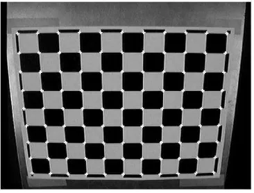
3.9 Original image of checkerboard 19
3.10 Matlab Analysis Toolbox 21
3.11 Object orientations and Rodrigues rotation vector 22
3.12 Setting calibration procedure 23
3.13 Intrinsic matrix equation formula 24
3.14 Extrinsic matrix equation formula 24
3.15 Calibration board with 40 coded fiducials 25
3.16 Image taking procedure using Omron F500 27
3.17 Camera mounted inside aluminium cube 28
3.16 Calibration stand 28
3.20 Calculating Average Effect 34 3.21 Calculating the Effect of the Two Concentrations of Factor 34
4.29 Bouquet Toolbox using Matlab 57 4.30 Zhang technique using Camera Calibration Tools 0.5.2 58 4.31 Heikeila technique using ReacTIVision calibration tool 59 4.32 Calibrate using Bouquet technique at x-axis 61 4.33 Calibrate using camera calibration tool at x-axis 62
4.34 Calibrate using Zhang technique at x-axis 63
4.35 Calibrate using Heikeila technique at x-axis 65 4.36 Calibrate using Bouquet technique at y-axis 67
4.37 Calibrate using Zhang technique at y-axis 69
4.38 Calibrate using Zhang Heikeila at y-axis 71
LIST OF TABLES
3.1 Omron F500 Camera Specifications 5
3.2 Stability of some extrinsic parameter 32
3.3 The Signal to Noise Ratio Characteristic 35
4.1 Data taken from Bouquet calibration technique 60
4.2 Data taken from Zhang calibration technique 62
4.3 Data taken from Heikeila calibration technique 64
4.4 Data taken from Bouquet calibration technique 66
4.5 Data taken from Zhang calibration technique 68
4.6 Data taken from Heikeila calibration technique 70
5.1 Average value of pixel error at x-axis 73
LIST OF ABBREVIATIONS, SYMBOLS, SPECIALIZED
NOMENCLATURE
.ANOVA - Analysis of Variance CCD - Charge-Couple Device CAD - Computer Aided Design DLT - Close Form Solution DOE - Design of Experiment
MANOVA - Multivariate Analysis of Variance PCER - Per-comparison Error Rate
SPSS - Statistical Package Social Sciences S/N - Signal to Noise Ratio
CHAPTER 1
INTRODUCTION
1.1 Background
camera setups in various experiments, the calibration done with our camera setup may also serve as a demonstration of the calibration procedure for others. Most importantly, a camera calibration determines the measurement accuracy of the camera imaging system. Throughout the calibration process, possible sources of measurement errors may be identified. Doing a camera calibration will also verify the measurement repeatability and capability of the camera imaging system.
1.2 Problem Statement
1.3 Objectives
Those objectives evaluated are to assist and complete this project:
(a) To determine suitable calibration technique based on the camera selection. (b) To analyze the selected calibration technique based on the study.
1.4 Scope
This paper has a limitation and scope of research. This project is emphasizing on the calibration technique require for optical components in non-contact measuring system. The CCD camera for measuring part shall be studied in order to fulfill the measurement gap between millimeter and micrometer. All the necessary calibration technique such as using checker board grid object and so on will be studied through this project.
1.5 Project Outline
(a) Chapter 1 describes about project, problem statement, objective and scope of the study. Before conducting camera calibration, the problem statement should be identifying, in order to have clear target on the project.
(b) Chapter 2 briefly explained about the literature review related to the study which includes description on CCD camera, the functionality, calibration technique and so on.
(c) Chapter 3 defined the methodology in conducting the calibration technique. (d) Chapter 4 consists of the result and analysis towards the experiments carried
out.
(e) Chapter 5 construct by the discussion of the analysis gathered on the experimental process.
CHAPTER 2
LITERATURE REVIEW
2.1 Overview
This chapter will briefly introduce the literature research of this project. It is consisted of the CCD camera, concept, functionality and calibration method involve in CCD camera measuring system.
2.2 Charge-Coupled Device (CCD camera)
2.2.1 A Review of Current Research of CCD camera
Charge Couple Device (CCD) camera is one of the option for measuring part and detecting defect quickly. There are various types of products which can be measure using this kind of technology such as electrical and electronic parts. According to Abbas et al. (2006), the current research trends in CCD are on the parameters and calibration method which recently studied all these years.
In recent years, CCD camera researchers have explored a number of ways to improve the measuring efficiency including some unique experimental concepts that depart from the CCD traditional phenomenon. Despite a range of different approaches, this new research shares the same objectives of achieving more efficient measuring system with a structured illumination technique to determine the shape of 3D objects (C.W. Liao et al., 2007).
In CCD camera development, commonly calibration technique used in manufacturing area is by using the simplest calibration target image pattern which is a checkerboard image that consists of adjacent black and white squares. The easily identifiable features of this type of calibration image are the corners between the black and white squares. The pixel coordinates of the corners on the calibration image can be retrieved by corner finding computer algorithms. And the physical coordinates of the corners on the calibration target object can be determined by measuring the position of the corners with a scale or other more accurate methods. (Tsai, 2005)
2.2.2 Basic Principles of CCD camera measurement
The basic principle of CCD camera measurement is where the CCDs are quite linear, in the sense that the signal they produce in response to light is directly proportional to the number of photons collected. By contrast, photographic emulsion suffers famously from nonlinearities, collectively called “reciprocity failure,” that make it hard to calibrate accurately the conversion between signal and amount of incident light (Falls, 2000).
Therefore, the accuracy of the measurement depends on the lights that reflect back to the CCD camera after hit the object or product.
2.2.3 CCD camera functionality.
Manual inspection is limited when it comes to identifying objects, and the reason is that a person’s vision is easily influenced psychologically, physiologically, or by the external environment. Moreover, since using human eyes to measure the external appearance of the product is more time consuming, and different in standard each time under different inspectors, it does not meet the demand for automatic mass production. The quality control is unstable, and the inspection is not effective either; it could not even achieve the requirements for 100% inspection. Some of the product
can’t be inspected using contact measurement, because most of it is made of elastic
products. Therefore, a machine vision system is set up for a non-contact 3D range data measurement system by integrating a visual module with image processing, mechanism module, and a control module, and anticipates reducing measurement errors and the human inspection error factor. In other words, a development an inspection algorithm with 3D sensing of the cone geometry and feature analysis concerning the shape and concentricity need to be carrying out to meets customers’ demand that helps achieve an automated visual inspection system to replace manual inspection (C.W. Liao et al., 2007).
result the human activity .The respiratory, circulatory and digestive systems will suffer and pain will be produced at various levels of intensity. All these aspects justifies early concern for the human spine geometry by means of constant 3D non contact measurements .The CCD camera is one solution to this problem .It helps to locate several reference points on the spine both in dynamic or static modes (Marius. M).
Photogrammetric measurements are used in several Hi Tec industries like building simulators for low altitude air navigation. People who are experts in mathematics or computer sciences but not in photogrammetry prefer to do almost all of the photogrammetric works by themselves, using a full automatic procedure, based on computer programs for the all photogrammetric works, from conjugate point measurement, till DEM and orthophoto generation (U. Ethrog). By using sun’s trajectory, we can determine the co-ordinate (place) effectively.
Very sensitive imaging detectors such as CCDs are currently use in astronomy at practically all wavelengths from far-infrared (as long as 200 μm) to X ray (as short as 0.1 Å) (Falls, 2000). So, in term of astronomical functionality, the CCD usage is going grow day by day like a telescope usage.
2.2.4 CCD camera calibration technique.
There is several technique mentions by researchers, which may be used as a reference in order to complete the project. Some of the idea generate by the researcher implement good possibility of accurateness which can be used as a guide.