ISSN (Print) : 2320 – 3765 ISSN (Online): 2278 – 8875
I
nternational
J
ournal of
A
dvanced
R
esearch in
E
lectrical,
E
lectronics and
I
nstrumentation
E
ngineering
(An ISO 3297: 2007 Certified Organization)
Vol. 3, Issue 9, September 2014
BLDC Motor Control for Electric Vehicle
Based On Digital Circuit and
Proportional-Integral Controller
Bambang Sujanarko
Department of Electrical Engineering, University of Jember, Indonesia
ABSTRACT: This paper describes a simple circuit controller of Brushless Direct Current (BLDC) motor for electric
vehicle implementation. This control based on the function relationship between the Hall sensor logics and currents that should be supplied on each phase of the motor. The function then simplified using Karnaugh-Map method and implemented using digital circuit. Pulse Width Modulation (PWM) added to produce six triggers that used to regulate the inverter current. Proportional Integral (PI) control based on Ziegler–Nichols also added to PWM circuit to improve motor speed performance. The controller are successfully applied using Matlab-Simulink and simulation results show that the controller have simpler circuit and have better speed performance than conventional controller.
KEYWORDS: Brushless Direct Current, Electric Vehicle, Digital Circuit, Proportional Integral, Pulse Width
Modulation, Karnaugh-Map, Ziegler–Nichols.
I.INTRODUCTION
Electric vehicle have some advantages over internal combustion engine automobiles, including a significant reduction of air pollution, reduced gas emissions, and reducing energy dependence on diminishing oil reserves. Electric vehicle will use electricity stored in the battery to drive the motor, and the power can be recharged with electricity generation using renewable energy. From various electric motors, the most suitable motor for electric vehicle is BLDC motors, because these motors have high reliability, high power density, high efficiency, low maintenance requirements, low cost and lower weight [1].
BLDC motors are normally powered by conventional three phase inverters which are controlled based on the rotor positions information obtained from Hall position sensors or simply Hall sensors [1-3]. Three phase windings use one Hall Sensor each and provide three overlapping signals giving a 60° wide position range. Whenever the magnetic poles pass near the sensors, a high or low signal will produce to indicating North or South Pole is passing the pole. The rotor position information is used to generate six trigger signals for power inverter [1-5]. BLDC controls that convert Hall signals to six trigger signals frequently built using microcontroller. In these controls the software difficult to implemented for person who non familiar with microcontroller. BLDC controls with microcontroller on the market also have unsatisfactory performance, because a lot of these control frequently damage or not working properly because protection in the control system is too sensitive.
ISSN (Print) : 2320 – 3765 ISSN (Online): 2278 – 8875
I
nternational
J
ournal of
A
dvanced
R
esearch in
E
lectrical,
E
lectronics and
I
nstrumentation
E
ngineering
(An ISO 3297: 2007 Certified Organization)
Vol. 3, Issue 9, September 2014
II.LITERATURE REVIEW AND SYSTEM MODEL
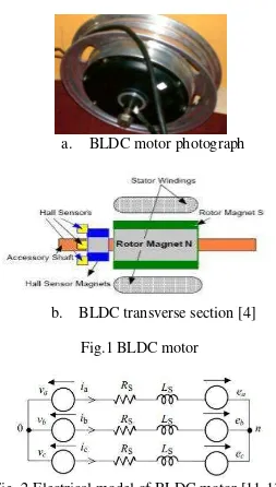
As the name suggests, the BLDC motor that also referred to as an electronically commutated motor, is not have brushes on the rotor, and the commutation is performed electronically at certain rotor positions. BLDC motor is driven by rectangular or trapezoidal voltage coupled with the given rotor position. The voltage strokes must be properly aligned between the phases, so that the angle between the stator flux and the rotor flux is kept close to 90 to get the maximum developed torque. BLDC motors often incorporate either internal or external Hall position sensors to sense the actual rotor position [1-7, 11-13]. Rotor position can also be detected without sensors [1-4]. Fig. 1 (a) shows BLDC motor photograph. In the research used 1000 W BLDC motor, 48 V and 950 RPM. This motor has main component stator windings, rotor magnet and Hall sensor as shown in Fig. 1 (b), that is a transverse section of BLDC. BLDC motor has model as shown in Fig.2.
a. BLDC motor photograph
b. BLDC transverse section [4]
Fig.1 BLDC motor
Fig. 2 Electrical model of BLDC motor [11-13]
Based on Fig.2 and if BLDC motor produce trapezoidal back EMF ea, eb and m, so the exited current ia, ib and ic waveform is preferably rectangular. If the series resistance winding Rs assume equal and the self and mutual inductance Ls also in equal, so the electric equation of BLDC motor is shown in equation (1) [11-13].
ISSN (Print) : 2320 – 3765 ISSN (Online): 2278 – 8875
I
nternational
J
ournal of
A
dvanced
R
esearch in
E
lectrical,
E
lectronics and
I
nstrumentation
E
ngineering
(An ISO 3297: 2007 Certified Organization)
Vol. 3, Issue 9, September 2014
For six step BLDC control, the power will be deliver from two phases as shown in equation (4), where I is the current amplitude and E is amplitude of back-EMF. Using equation (2) and (4), the electric torque can also express as equation (5), where kt is motor torque constant [11-13].
Complete BLDC drive system shown in Fig. 3. This system usually consists of BLDC motor (5), inverter (1), Hall Effect sensors (4), controller (3) and driver circuit (2) [13]. The position sensor (4), usually Hall sensor, give sign of position the permanent magnet in the windings. These positions generally indicate using three bits data. These data then entered in a control circuit (3) to convert in the 6 trigger signals for inverter (1), which usually composed from power device like MOSFET or IGBT. In the control circuit, the trigger signals also regulate to desire direction and speed of rotation. Before enter to the inverter, the trigger signals entered to the driver circuit (2). In this circuit, the signals will be matching to the switch devices. Finally, by condition of switch of inverter, the power flow to windings. Hall sensor then detects new position and the process will be return to control circuit.
Fig.3 BLDC drive system [13]
Fig.4 Back-EMFs, current and Hall position sensors waveform of BLDC motor [13]
ISSN (Print) : 2320 – 3765 ISSN (Online): 2278 – 8875
I
nternational
J
ournal of
A
dvanced
R
esearch in
E
lectrical,
E
lectronics and
I
nstrumentation
E
ngineering
(An ISO 3297: 2007 Certified Organization)
Vol. 3, Issue 9, September 2014
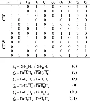
until 150o, the 3th in 150o until 210o, the 4th in 210o until 270o, the 5th in 270o until 330o and the 6th in 330o until 30o [13]. The relationship among waveform can be expressed using Table 1 [13]. In this table, Dir. is direction rotary of BLDC motor, if Dir.=1, the direction is in the right, otherwise if Dir.=0, the motor direction is Left. Together with Hall A, Hall B and HallC, the current in the motor can generate using give trigger on Q1 until Q6 ON or OFF. Logic 1 means ON and logic 0 means OFF. Using Karnaugh-Map simplification, this table produces a simple logic function in equation (6)-(11) [13].
Table 1 Relationship among direction, the position of Hall sensor and switching in the inverter
Dir. HC HB HA Q1 Q2 Q3 Q4 Q5 Q6
C
W
1 1 0 1 1 0 0 0 1 0 1 1 0 0 0 0 1 0 1 0 1 1 1 0 0 0 1 1 0 0 1 0 1 0 0 1 0 1 0 0 1 0 1 1 0 1 0 0 0 1 1 0 0 1 1 0 0 0 0 1
C
C
W
0 0 0 1 0 0 1 1 0 0 0 0 1 1 0 0 1 0 1 0 0 0 1 0 1 0 0 0 1 0 0 1 1 0 1 0 0 0 0 1 0 1 0 0 0 1 0 0 0 1 0 1 0 1 0 1 0 1 0 0
1 DirH HB A DirH HB A
Q (6)
2 DirH HC B DirH HC B
Q (7)
3 DirH HC A DirH HC A
Q (8)
4 DirH HB A DirH HB A
Q (9)
5 DirH HC B DirH HC B
Q (10)
6 DirH HC A DirH HC A
Q (11)
In a BLDC, there are two phases simultaneously active with square wave excitation and in the magnet distance approximately equal to the pole arc, the electric torque (Te) is given as equation (12) [13]. Substitute equation (12) to (2), the angular speed of BLDC motor can be arranged into equation (13). If V produce from voltage supply (Vs) using PWM method with D duty cycle, the voltage (V) can calculate using equation (14) [13] and finally become equation (14).
Te Np N Nt spp P I Br Lx Rx (12)
3 k
EI
k kV
Np N Nt spp P I Br L R
E
(13)s
kDV (14)
To improve BLDC speed in the better respond and stability, BLDC controller equipped with Proportional Integral (PI) controller. P and I Constanta can determine using various methods. Among these methods, Zieger-Nichols method is the simplest. Ziegler-Nichols method has two types, i.e. the closed loop method and open loop method. Tuning of Zieger Nichols accepted in stability region, if the ratio of the amplitudes of subsequent peaks in the same direction (A2/A1) is approximately 1/4. Fig.5 (a) show open loop respond of system that accepted using Zieger-Nichols tuning and Fig.5 (b) shows how to determine parameters in the Zieger-Nichols tuning. While Table 2 shows equation of constanta of PID controller using Zieger-Nichols. Using Fig.5 and Table 2, Kp, Ti and Td can calculated.
ISSN (Print) : 2320 – 3765 ISSN (Online): 2278 – 8875
I
nternational
J
ournal of
A
dvanced
R
esearch in
E
lectrical,
E
lectronics and
I
nstrumentation
E
ngineering
(An ISO 3297: 2007 Certified Organization)
Vol. 3, Issue 9, September 2014
b. Parameter
Fig.5 Open loop responds of system that accepted and determine of parameter using Zieger Nichols tuning
Table 2 Equation constantas of PID controller using Zieger Nichols
III.SIMULATION CIRCUIT
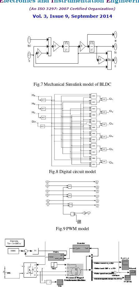
If back-EMF of BLDC assume have 120 degree phase shift with respect to each other and all phase current is equal, so based on equation (1) until (3), the state space BLDC is shown in equation (15) and (16) [12]. Implementing these state space equations will make model more complex, therefore these equation is divided to two simple models, that is electrical and mechanical model. Using Simulink Matlab these model shown in Fig.6 and Fig.7. Control unit of BLDC drive system consist of digital circuit and PWM circuit. Implementation of digital equation (6) until (11) is shown in Fig.8 [13]. While PWM circuit as result of equation (14) is shown in Fig.9. Using load of electric vehicle modeled on simulink block and inverter on Universal Bridge. Simulation model of BLDC motor for electric vehicle is shown in Fig.10.
(15)
(16)
Fig.6 Electrical Simulink model of BLDC 3 Te 2 m 1 i
Vab,Vbc Eabc
is
State
the Hall
Hall
the,we E abc
phi'r abc
BEMF, Flux
-K-.. .
3 the
2 we
ISSN (Print) : 2320 – 3765 ISSN (Online): 2278 – 8875
I
nternational
J
ournal of
A
dvanced
R
esearch in
E
lectrical,
E
lectronics and
I
nstrumentation
E
ngineering
(An ISO 3297: 2007 Certified Organization)
Vol. 3, Issue 9, September 2014
Fig.7 Mechanical Simulink model of BLDC
HA HB HC Dir Q1 Q2 Q3 Q4 Q5 Q6
Fig.8 Digital circuit model
Fig.9 PWM model
Fig.10 Simulation model of BLDC motor for electric vehicle
3 m 2 the 1 we Mux -K--K- K Ts
ISSN (Print) : 2320 – 3765 ISSN (Online): 2278 – 8875
I
nternational
J
ournal of
A
dvanced
R
esearch in
E
lectrical,
E
lectronics and
I
nstrumentation
E
ngineering
(An ISO 3297: 2007 Certified Organization)
Vol. 3, Issue 9, September 2014
Fig.11 Relationship among Hall signal waveform, back-EMF and BLDC motor current
IV. RESULT AND DISCUSSION
Control circuit can produce signal equal to the expectation waveform. Fig.11 show relationships among Hall signal waveform (HallA-HallC), back-EMF (ea-ec) and BLDC motor current (Ia-Ic). This relationship show that the proposed control produce correct function. In this figure, the parameter amplitudes were adjusted to give a proportional figure. Beside produce correct signal, the proposed control also produces a simple circuit. The digital circuit on Fig.8 can implement using TTL or CMOS digital IC, as example IC TTL 7408 or IC CMOS 4073 for AND gate, IC TTL 7432 or IC CMOS 4071 for OR gate.
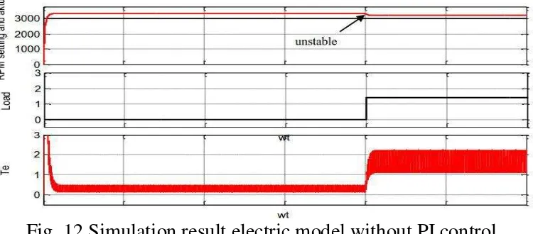
Fig. 12 Simulation result electric model without PI control
PWM circuit can implement using Opamp circuit. This circuit consists of triangle wave generator and a comparator that compare DC voltage setting and triangle signal from triangle generator. The result of this circuit is PWM signal trigger that duty cycle regulated for power electronic device in the low position. Using adjust the DC voltage setting, the current of the BLDC motor can regulated, so the motor speed can also regulated easily.
Fig.13 Simulation result electric model using PI control
ISSN (Print) : 2320 – 3765 ISSN (Online): 2278 – 8875
I
nternational
J
ournal of
A
dvanced
R
esearch in
E
lectrical,
E
lectronics and
I
nstrumentation
E
ngineering
(An ISO 3297: 2007 Certified Organization)
Vol. 3, Issue 9, September 2014
calculate first using Table 2. Before and after the load cahnges from 0 to 1.5 N, the speed of BLDC motor sable on setting 3000 RPM.
V.CONCLUSION
BLDC motor control for electric vehicle can design using a simple digital circuit. Using Karnaugh-Map simplification of Hall position signal and current of motor that realized on gate trigger of power semiconductor switches, this circuit easy to build and can produce control signal like other controls. To regulated speed and improve performance, a PWM and PI control added to this digital circuit. Result simulation show that this control has good performance, because in the dynamic load the speed can stable and regulated on setting point.
REFERENCES
1. Ali Emadi, “Handbook of Automotive Power Electronics and Motor Drives”, Taylor & Francis Group, CRC Press, 2005. 2. Padmaraja Yedamale, “Brushless DC (BLDC) Motor Fundamentals”, Microchip Technology Inc., 2003
3. Sathyan, A., Milivojevic, N., Young-Joo Lee, Krishnamurthy, M.; Emadi, A., “An FPGA-Based Novel Digital PWM Control Scheme for BLDC Motor Drives”, Industrial Electronics, IEEE Transactions on, Vol.: 56, Issue: 8, pp.: 3040 – 3049, 2009.
4. Atmel Corporation, “AVR498: Sensorless control of BLDC Motors using ATtiny261/461/861-Application Note”, Atmel Corporation, 2009. 5. Bambang Sujanarko, “Brushless Direct Current (BLDC) Motor Controller Using Digital Logic For Electric Vehicle”, National Conference
ReTII ke-7 Tahun 2012, STTNAS Yogyakarta, 2012.
6. Bambang Sujanarko, “Desain Kontrol PWM Pengatur Kecepatan Motor BLDC Untuk Mobil Listrik”, National Conference Semantik Tahun 2013, UDINUS Semarang, 2013.
7. Padmaraja Yedamale, “AN885 Brushless DC (BLDC) Motor Fundamentals- Application Notes”, Microchip Technology, 2003. 8. The MathWorks, “Matlab Guide”, MathWorks, Inc., 2013.
9. Loeb, M.L., Rindos, A.J., Holland, W.G., Woolet, S.P., “Gigabit Ethernet PCI adapter performance”, Network, IEEE, Vol. 15, Issue: 2, pp. 42 – 47, 2001.
10. Advantech, “PCI-1711/L Entry-level 100 kS/s, 12-bit, 16-ch PCI Multifunction Card”, Advantech. 11. Krishnan. Rramu, “Electric motor drive: modeling. Analysis and control”, Prince Hall. Inc., 2001
12. Bhim Singh and Sanjeev Singh , “State of the Art on Permanent Magnet Brushless DC Motor Drives”, Journal of Power Electronics, Vol. 9, No. 1, 2009
13. Bambang Sujanarko, Bambang Sri Kaloko, Moch. Hasan, “BLDC Motor Control Using Simulink Matlab and PCI”, International Review of Modeling and Simulations (IREMOS), Vol. 6, n. 6, December, 2013

![Fig.3 BLDC drive system [13]](https://thumb-ap.123doks.com/thumbv2/123dok/1250462.697267/3.842.287.560.602.1003/fig-bldc-drive-system.webp)


