UNIVERSITI TEKNIKAL MALAYSIA MELAKA
INTELLIGENT RECEIVING BOX INTEGRATED
WITH GSM NETWORK
This report submitted in accordance with requirement of the Universiti Teknikal Malaysia Melaka (UTeM) for the Bachelor‟s Degree of Engineering Technology
(Department of Electronics & Computer Engineering Technology) (Hons.)
by
NUR LIYANA BINTI AZIZAN B071110023
901015-05-5142
UNIVERSITI TEKNIKAL MALAYSIA MELAKA
BORANG PENGESAHAN STATUS LAPORAN PROJEK SARJANA MUDA
TAJUK: Intelligent Receiving Box Integrated with GSM Network
SESI PENGAJIAN: 2014/15 Semester 1
Saya NUR LIYANA BINTI AZIZAN
mengaku membenarkan Laporan PSM ini disimpan di Perpustakaan Universiti Teknikal Malaysia Melaka (UTeM) dengan syarat-syarat kegunaan seperti berikut:
1. Laporan PSM adalah hak milik Universiti Teknikal Malaysia Melaka dan penulis. 2. Perpustakaan Universiti Teknikal Malaysia Melaka dibenarkan membuat salinan
untuk tujuan pengajian sahaja dengan izin penulis.
DECLARATION
I hereby, declared this report entitled “Intelligent Receiving Box Integrated with GSM Network” is the results of my own research except as cited in references.
Signature : ………
Author‟s Name : Nur Liyana Binti Azizan
APPROVAL
This report is submitted to the Faculty of Engineering Technology of UTeM as a partial fulfillment of the requirements for the degree of Bachelor of Engineering Technology (Bachelor‟s Degree in Electronics Engineering Technology (Telecommunications)) (Hons.). The member of the supervisory is as follow:
………
Mrs. Eliyana Binti Ruslan (Principal Supervisor)
………
i
ABSTRAK
ii
ABSTRACT
In the late 18th centuries, the industrial revolution brought about major changes in manufacturing, mining, communications, transportations, electronics and agriculture sectors. Those days there are so many services or systems that can help human to ease their work or life. The Intelligent Receiving Box Integrated with Global System for Mobile (GSM) Network is different from other pigeon holes that were selling in the market. It will allow the owner to be notified anytime and anywhere through receiving a message. The users of the intelligent box just have to wait and collect their important documents. The most important component of the
project is the microcontroller that acts as the system‟s master mind which ultimately
controls the system through a “Pro programming”. The controlling unit is the Peripheral Interface Controller (PIC) 16F877 microcontroller. Consequently, if the sensor has triggered, the PIC will process the received data from the sensor and will also be responsible for sending the output to the Liquid Crystal Display (LCD) screen that will display the total amount of documents. Additionally, it will have a power supply and also a rechargeable battery as a backup. This intelligent receiving box system is designed to use a GSM network. The PIC, will be programmed, thus it will carry out the program to be able to count the documents and send a notifications through a mobile phone.
iii
DEDICATION
To my beloved parents,
iv
ACKNOWLEDGEMENT
vi
2.4.10.1 General Purpose Relay 36
2.4.10.2 Mechanical Control Relay 36
2.4.10.3 Reed Relay 36
CHAPTER 3: METHODOLOGY 37
3.1 Introduction 37
3.2 Block Diagram 41
3.3 Operation of the Block Diagram 42
3.4 Overall Flow Chart 43
3.9.1 The Structure of C Programming 54
3.9.2 Flow Chart for Programming 56
3.9.2.1 Main Circuit Flow Chart 56
vii
CHAPTER 4: RESULT & DISCUSSION 62
4.1 Introduction 62
4.2 Power Supply Circuit 62
4.3 Display Circuit 63
4.4 Sensor Circuit 66
4.5 Keypad Circuit 67
4.5 Solenoid Circuit 67
4.7 Tested Send SMS to Hardware by using AT Command 68
4.8 Sending Message to Mobile Phone Analysis 69
CHAPTER 5: CONCLUSION & FUTURE WORK 71
5.1 Introduction 71
5.2 Conclusion 71
5.3 Suggestion 72
REFERENCES 74
APPENDICES 76
viii
LIST OF TABLES
2.1 Existing Project Features Comparison 16
2.2 PIC16F887 Pin Description 20
2.3 Comparison between PIC16F887, PIC16F84A and PIC16F876 20
2.4 AT89C51 Pin Description 21
2.5 A Timeline of the Development of GSM 24
2.6 Features of the GSM Modem 26
2.7 Comparison of LCD Categories of their Pros and Cons 27 2.8 Comparison between LCD, Mobile Phone & Persona Computer 30
2.9 Functions each Pin of LM7805 34
4.1 The Output Measurement for Power Supply in Each Circuit 63
4.2 Push Button Testing 63
4.3 Push Button Testing (cont.)
4.4 Measurements Voltage of Keypad Circuit at the Output Pin of AT89C51
67
ix
2.5 GSM Smart Mail Box Circuit Connection 12
2.6 IR Sensor (Infrared Sensor) 13
2.12 PIC16F887 Pin Description 19
2.13 The Pin Layout of the AT89C51 22
2.14 MAX232 22
2.15 The Description Each Pin of IC MAX232 23
2.16 Wavecom Fastrack GSM Modem with Other Accessories 26
2.17 An Example of 16×2 LCD 28
2.18 An Example of a Schematic 16×2 LCD 29
2.19 Keypad 4×4 30
2.20 Keypad row/column Matrix 31
2.21 Solenoid Door Lock 32
2.22 Description LM7805 of Each Pin 33
2.23 LM7805 34
2.24 A Diagram Circuit Inside of A Relay 35
2.25 Relay 9Volt (General Purpose Relay) 36
3.1 The Methodology of This Project To Finish 38
x 3.3 The Methodology of This Project To Finish (cont.) 40
3.4 System Block Diagram 41
3.5 The overall Flow Process 42
3.6 Overall Flow Chart for Counting Documents & Sending Message 44 3.7 The Overall Flow Chart for Security Input Password 45
3.8 Main Circuit of GSM 46
3.9 Security Keypad Circuit 47
3.10 The Prototype of This Project 48
3.11 Completed Hardware of Main Circuit GSM 48
3.12 Completed Hardware of Security Circuit 49
3.13 Top View of The Infrared Sensor 50
3.14 Bottom View of the Infrared Sensor 50
3.15 Process of Compiling Coding for Main Circuit 51
3.16 Process of Compiling Coding for Security Circuit 52
3.17 SK40C and UIC0BB 53
3.18 The Hex File Were Successfully Loaded Into The PIC 53
3.19 Flow Chart for Display Menu 56
3.20 Flow Chart for Mode 1 57
3.21 Flow Chart for Sensor 58
3.22 Flow Chart for Sending Message Process 59
3.23 Flow Chart for Security Circuit 60
3.24 Flow Chart for Security Circuit (cont.) 61
4.1 LCD Display “GSM MODEM READY” 64
4.2 LCD Display PHONE NUMBER 0124801202 64
4.3 LCD Display No of Count 002 65
4.4 LCD Display Clear Document? No/Yes 65
4.5 Infrared Sensor Distance Measurement 66
4.6 AT Command in Order The Message to be Send 69
xi
LIST OF ABBREVIATIONS, SYMBOLS AND
NOMENCLATURE
IRB - Intelligent Receiving Box SMS - Short Message Service
SIM - Subscriber Identification Module
RF - Radio Frequency
RFI - Radio Frequency Identification LED - Light-Emitting Diode
EEPROM - Electrically Erasable Programmable Read Only Memory
A/D - Analog To Digital
TDMA - Time Division Multiple Access FDMA - Frequency Division Multiple Access 3G - Third-Generation (3G) Network 4G - Fourth-Generation (4G) Network
LTE - Long-Term Evolution
1 Chapter 1 will be discussed about an introduction of the project. The main idea is
about the background and objectives of the project will be discussed.
1.1 Project Background
Nowadays, pigeon hole seem to be the most important system for submitting
personal document or student‟s assignments in a university. Commonly pigeon hole used by lectures but however regular people who work in an office are also regular user of pigeon hole or others might called it as a mail box. In order to receive an important document without worrying it will be lost or stolen, it must be able to register the receiving document and alert the owner. The intelligent receiving box acts like a pigeon hole but it is different from normal pigeon holes that are sold in the market.
Although there is a lots of expensive pigeon hole in the market still, it is not
guaranteed that it will satisfy most of the customers‟ needs. With the aid of a
technology that will be incorporated into the pigeon hole box this will improve and expand a lot of functions and also can reduced the problems that most user will encounter such as loss of important documents. Intelligent Receiving Box (IRB) is the new generation of a pigeon hole. IRB is able to notify the owner through Short Message Service (SMS) and at the same time it will notify the total amount of document that the user receives by end of the day. User can set whether to notify by specific time intervals or ended of working time.
2 By using the infrared (IR) sensor, it will detect the document that relayed or inserted into the box. After the sensor has triggered, it will automatically send information to the PIC to be accounted. The infrared sensor will count the total number of documents based on the total amount of insertions made. Subsequently, it will display on the liquid crystal display (LCD) screen the total amount of the documents in the IRB. The proposed system consists of two parts, namely the transmitting unit and receiving unit. The Transmitting unit involves a sensor and microcontroller that will transmit the signal to the Global Service for Mobile Communication (GSM) Modem when the sensor is triggered.
After the GSM has transmitted according to the user‟s specification, then it will
receive the signal or Short Message Service (SMS) through the owner mobile phone. The Peripheral Interface Controller (PIC) will be programmed to detect input and
send output to the owner‟s mobile phone. In addition added security features will be
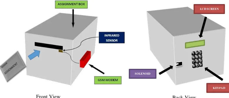
incorporated into the intelligent receiving box so as to fortified security and to avoid data tampering or invasion. This will make the user of IRB to feel more secure and safe about their important documents. By using a keypad 4x3 input, it is easy for the user to enter their password. After entering their password correctly the box will automatically unlock the door. In Figure 1.1 shows the layout of this project.
Figure 1.1: Layout of Intelligent Receiving Box
SOLENOID
LCD SCREEN
KEYPAD
3
1.2 Problem Statement
Loss of documents and unaware receiving important documents can at times caused huge problem to the user. Imagine important documents that need urgent attention are unattended immediately because the users are not alerted or aware about it. This sometime will cause miss opportunity especially if it involved business dealings‟ documents. Thus based on this problem, there is certainly a need to develop the Intelligent Receiving Box or IRB. IRB will provide the impeccable security system for deposited documents and at the same time will ensure that any received documents will be alerted to user on real time basis. IRB will also filter and ensure that documents delivered are for the intended recipients only. Obviously IRB will instil confident among student knowing that their assignments or documents sent to their respective lectures are safe and secured.
This proposed project also has some limitations because this GSM modem operates just like how a cell phone operates. It will able to operate or send a SMS when the SIM attached in. However, the user needs to top up the Subscriber Identity Module for a mobile phone (SIM) regularly to maintain its operation period validity. Another important limitating element for a GSM modem is that the system needs a good coverage to make the process of sending SMS happens quickly without any interruption.
4
1.3 Objectives
The objectives of this project are to:
a) develop and implement an intelligent receiving box, which uses Global System for Mobile Communication (GSM) modem to send the Short Message Service (SMS) to the owner.
b) demonstrate this system can count the amount of assignment inserted in the box with an additional infrared sensor
c) design a user friendly interface and where the user can easily understand the instructions of the product.
d) study the art of programming in C language and C++ language.
e) focus on all hardware skills, electronic knowledge and technology idea with some software development in building this project.
1.4 Scope of Work
This project will focus on these few scopes. Firstly, on the Global System for Mobile Communication (GSM) must support all the numbers whether it is under the telecommunication provide such as Celcom, Digi, Maxis or others. Secondly, it will focus on the PIC programming using PIC16F887 and the combination of all components in a circuit.
5
1.5 Project Significance
By inventing this intelligent receiving box, it will gives a lot benefits to students and lecturers. Students are able to send their assignments without worrying that the assignment will be loss or stolen by other students. Other than lecturers also will gain some benefits such as they can be notify if the assignments or documents is not the right amount to be receive. In addition, the system will send SMS the total amount of assignments or documents should be receive in a certain period. Moreover this application can also be implemented in the offices or libraries. Lastly, the contribution of this project is the real time alert system that uses Global System for Mobile Communication (GSM) modem to send the Short Message Service (SMS) to the user and the technology of the infrared sensor that is able to sense a document or assignment entered through the hole of the box.
1.6 Thesis Structure
Chapter 1 will discuss about the introduction of the project. The background and objectives of the project will be discussed in this chapter.
Chapter 2 will cover the literature reviews of the project. This chapter will elaborate the concept of the research involved, the differences between projects to the related field and various types of components that are utilized in this project.
Chapter 3 will detail out the methodology and process that will be under taken to complete the project. This chapter will elaborate the detail development of this project such as the equipment used, software development and others.
7 Chapter 2 will cover the literature reviews of the project. This chapter will elaborate the concept of the research involved, the differences between projects to the related field and various types of components that are utilized in this project.
2.1 Introduction
This chapter will discuss the overall overview of the project - the Intelligent Receiving Box Integrated with GSM Network. This Intelligent Receiving Box is the new improved technology that is applied or incorporated to the normal pigeon hole box. In addition, this project is the solution for the problem statement that was stated in chapter 1. Once these ideas are expressed then the next crucial step is to evaluate whether these ideas are achievable or not. This can only be done by summarizing previous research on related topic and this step it is also commonly known as literature review. The purpose of literature review is to list out the strength and weakness of an established idea and knowledge to the reader. It also shows the method used and the selection of devices and software to build up other related systems. The literature review can be either from thesis, scientific journals, part of research project and current or existing system.
8
2.2 Project Review
Although there are many pigeon holes product on the market currently, but none of these products have the features of the Intelligent Receiving Box Integrated with GSM Network. Therefore, based on the literature review that has been extensively carried out it could be concluded that Intelligent Receiving Box Integrated with GSM Network is a new such technology to be developed. Without any previously developed technology or system to base upon, the task of building or inventing the Intelligent Receiving Box Integrated has to start with focusing on hardware structure, system design and implementation. Here are some projects obtained from online survey and that are found to have some basic connection to this project.
2.2.1 RFID and GSM Mailbox
This project is made by Madhan Mohan Reddy B that implements a RFID tag to the courier and sends the identity number to the receivers mobile. The receiver of the courier will have a letter box which has a Radio Frequency (RF) reader and a dedicated GSM modem in it. As soon as the courier boy drops the letter into the mailbox, the RF reader reads the identity number of the tag and informs the same to a micro controller. Next it will then compare it with the identity number send by the courier office and if both the same then it sends message to the receiver and also to the courier office about the arrival of the courier. This system has used a microcontroller which acts as a medium of communication between the RF reader and the GSM modem.
Other than that, by looking at the design of this project, the whole system also requires a microcontroller. The PIC is the important part which will function as the
9 with the receiver anywhere. Although this project has advantages, however this project also have some disadvantages too.
The advantages of this project are that, it is not suitable to place a RFID tag on each letters. Other than that, if the letters have defects of the RFID tag, this system may not sense the tag at the mailbox and will not operate properly. Lastly, this project does not implement the security to keep the letters safe. In Figure 2.1 is the example project of RFID and GSM Mailbox.
Figure 2.1: RFID and GSM Mail Box