Jurnal
Teknologi
CODING TEMPLATE
OF
SENSORLESS SUN TRACKING
USING AZIMUTH-ELEVATION MODE
Article history
Received 15 February 2015 Received in revised form 30 April 2015 Accepted 31 May2015
I. Norain·, Z. M. Zultattah, A. Erny Zairah, Halyani M . Y., H. M. S.
Firdaus
0Department of Mechanical Engineering Technology, Faculty of
Engineering Technology, Universiti Teknikal Malaysia Melaka,
Melaka, Malaysia
*Corresponding author
Graphical abstract
S..00
-1s.oo
r
uo.oe
75.00
10.00 • .
uu.oO < RHO.GO
1.0 INTRODUCTION
10. 00
8.00
Abstract
The next explosion in solar power research was in 1997 as consequence to Kyoto Protocol. This protocol outlined the effect of greenhouse emission which endangers ourEorth. As the resotf; research in solarpowerfieldstorted to lali::e its path again. This work is a port of the UTeM project to buHd the first CST model in South East Asia and was aimed to develop an azimuth-elevation-mode4:>ased template using MATLAB programming for the calculation of the heliostat position with respect to ffie heat absorber mounted at the top of the CST. This template -will serve as the catculolton platform to control the movement of the heliostat using a two-axis motion system so that ffie sun light
wil be redirected perfeclly to the absorber oH day long. Since the hefostot normal vector depends on sun position vector. both vectors were calculated by the program and were set as the output of the program. The input from the user wil be the Cartesian coordinate ot the heliosfot and absorber by taking the absorber tower frontal surface and its base as the origin and also the dote. The result wil be in vector form and wil change automaticaly according to the Sun movement. These values 'Wll be programmed in the micro controller which wil control the motion system of the heiostat. which will be done by the Control Department of UTeM. The program' s functionality was proved via several verifications and its accuracy which is 0.0005 as stated and verified via comparison with analytical calculations. From the verifications. it can be seen that difference of the numerical and analytical results varied from 0.0000 ta 0.0005 which validates the siolemenl of minimum accuracy of the numerical calculated resufu is 5/10,000.
Keywords: Heliostat. sun frocking. azimuth-elevation. code
© 2015 Penerbit UTM Press. All rights reserved
Sunlight that reaches the Earth is spread out over such a large area. Basically, the Sun does not deliver that much energy to one place at one time [1 ] . Solar energy received at a p lace depends on several conditions. They actually act as limitations in solar energy capturing process. These includes the time of the day. the season of the year. the latitude of area and the clearness or cloudness of sky. Via Conc entrating Solar Power (CSP) tec hnology . the
solar e ne rgy is multiplied from several time to few thousand time as it is concentrated onto a certain size of area before it is converted into electric power. The concentrated sun irradiation is multiplied several times (vvhich is around 600 to 1000 times) producing very high temperature. The temperature is in the range of 800°C to l 000°C [8].
The Concentrating Solar Power system con be divided into two types of system 'Nhich ore line focusing and point focusing. The point focusing system produc es higher temperature concentration
86 I. No rain et al. / Jumal Teknologi (Sciences & Engineering) 76:5 (20 I 5) 85-88
as sun irradiation is focused on one point compared to line. It also has higher efficiency compared to its counter system [8]. Examples of point-focusing CSP technology are dish stirling and concentrated solar tower (CST) system. There are Malaysian researches involving heliostat.
In 2001, UTM suggested a design for a single layer
sun-ray concentrator, a non-imaging focusing
heliostat. The design uses several small mirrors to form a heliostat to reduce first order image defect [2]. Malaysia University of Science and Technology (MUST) worked on residual aberration for non-imaging focusing heliostat in 2003 [3]. Universiti Tunku Abdul Rahman (UTAR) denved general formula of system for all existing-method on-axis sun-tracking system in 2009 [4] . In 20 11, they did a comparison between the two methods of sun tracking, which are Azimuth-Elevation and . Spinning-Elev ation methods
[5] .
This work is part of the feasibility study and CST mini model generation project and is aimed to develop a template using MATLAB programming for the calculation of the heliostat position with respect to the heat absorber mounted at the top of the CST
via azimuth-elevation mode. This is done by
calculating sun position vector and heliostat normal vector based on the calculated sun position by implementing the developed MATLAB code. The
developed code vJiU then be utifized by other UT eM
team to realize the azimuth-elevation mode of sun tracking of the heliostat of mini CST project.
The input from the user will be the Cartesian coordinate of the heliostat and absorber by taking the absorber tower frontal surface and its base as the origin and also the date. The result will be in vector form and will change automatically according to the Sun movement. These v alues will be programmed in the micro controller vvhich will contml the motion system of the heliostat.
2.0
EXPERIMENT AL
The theory behind sun-tracking procedures and its corresponding calculation are well understood. The related calculations are inter alia sun position, azimuth angle, heliostat normal. the Sun irradiation redirection vector.
An analytical calculation of a sample case is then done as reference values to ensure that the output values from to-be-developed code are correct. Only after achieving this, the code can be developed.
Every calculation step which is taken from the theory part should be converted to MATLAB code. The input should be the date (no. of month and no. of day are e ntered separately). the Cartesian coordinate of heliostat. the Cartesian coordinate of the tower. Latitude is set as a fixed value in this code, which is the latitude of UTeM. Whereas outputs are sun position and heliostat mirror normal v ector. The code is developed for the utilization between 7 a .m .
and 7 p .m. as the Sun is assumed to be only available during this time range.
The verification of the result is done b y testing the code of several different dates and comparing the outputs with analytical calculation for several cases of different dates with selected solar time. The accuracy of the calculated numerical results will be found and stated afterwards by comparing them with analytical calculated results. The code is then ready to be used after all the verification processes are done.
Theory of Sun Position and Hellostat Normal
Calculation
The components_9f h eliostat normal vector are inter
alia sun position
S
and redirection of Sun ray vectorR
and angle of Sun ray incidence on mirror andangle of redirection of the Sun ray towards the receiver (since angle of incidence and reflection
have the same value) or denoted as
e.
Refer Fig ure1.
In a two-component gel, it is easy to modify the molecular structure of either of the two components.
'
: Ys
' .
,
..
'(ttslJ
(hdomt norlTlll)
H
z (zenith)
87 I. No raln et a l. / Juma / Te kno logi (Scienc e s & Eng ineering) 76:5(2015) 85-88
sua
セ@
5.00
-N
s
75.00
r
10.00
m
x 130.00 8.00
セNPP@
10.00
130.00 (
[image:3.600.302.553.87.540.2] [image:3.600.52.293.88.445.2]Rl50.00
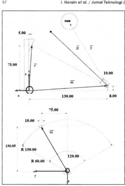
Figure 2 Sketch of side and top view of CST and its coord inate systems
It is important to not e the coordinate system used before calculations are proceeded. Based on the Figure 2. hefostat or mirror and receiver or also known as absorber vectors utilize the tower base as
referenc e . The vectors are d e noted a s
m
and ;respectively and these vectors are user's input. The x-axis lies right under the tow er base itself, whereas z-axis coincides with the front surface of the tower. if both axes are observed from the side view of the tower. Y-axis lies in the middle of the tower if it is observed from bird's ey e view.
Based on Figure 2. ウオセ@ position vector
S
andheliostat normal vector
N
take the center of theheliostat as the origin. These two vectors are the output o f the developed program. In other words, there are two different origin used in the calculation.
To calculate sun position for a certain day. the
date of the day must be known and be provided to determine the nth day of the year.
With the known solar 。ャエ ゥ セ、・@
as
and a zimuth angleYs
the sun position vector 5 with respect to horizontalsurface at any p oint on the Earth can be determined using below formula :
Sz
=
S z
=
sina
5 ,5
11=
S Y
=
cos
a5sin }'
5 ,Sn = 5 %
=cos
as
CO S J's(I)
The law of specular reflection is applied in the redirection of the Sun ray calculation. This law states that the angle of incidence is equal to the angle of reflection.
セ@
(no) (zo)
Receiver vector,
r
=
eo
=
Yo ;z o z o
セ@
(":) {
ク セ I@
Mirror vector.
m
=
[ セ@=
|[ ᄋ セ@;
Redirection of the Sun ray vector.
R
= [
MッMコ エ Iゥ セ H ッ M •) j+(no- 11:H]セ ャ {gヲッM z : ) · +(•o- エ I GQ KH セ M n:.) · ]
The scalar point between the vectors of 5 e nd
R
results in cosines of two-time angle of incidence
8
like in follo'Mng expression:
cos28
=
S.R
=R
3sin
a s +
R.
cos
as
sin y
5+
Rn
cos
a s cos ys
N
is a normal vector of heliostat at a moment. atwhic h sun ray arrives parallel to the v ecto r 5 a nd the ray is reflected onto the receiver or absorber.Jt can be calculated via addition of incidence 5 and
reflection vectors
R
and via division of the addedvector values with the suit able scalar quantity:
N
=
[CRz+5% ) i ( R,+ S11) j+ ( R,i5,i )ic]
2 coe9
where component x is denoted by unit vector
k,
component y is denoted by unit vector
J
andcomponent z is denoted by unit vector
i
along north.east and zenith direction respectively.
3.0 RESULTS AND DISCUSSION
In developing the code. several important
parameters which determine the sun position and the resulting heliostat normal such as the date of a certain day . heliostat and rec eiver position are set as variables. so that user can determine the input a s needed. For example. the date must be keyed in to
(2)
(3)
88 I. Noroin et a/. I Jumal Teknologi (Sciences&. Engineering) 76:5 (2015) 85-88
tell the program what day it is to dete rmine nth day of the year and celestial declination/inclination 6.
The celestial declination/inclination 6 is a necessary
component for sun position vector calculation. Different day gives different sun position. This explains the reason of the date being important to be set as a variable. Whilst heliostat and receiver positions are also set as variable since both vectors depend on the heliostat field design and layout. Therefore. this program can be used for an independant single heliostat. which its position is determined by user. The output of lhis programme ore sun position of a c ertain day and also the corresponding heliostat normal. so that incident sun ray will be reflected exactly on the receiver.
Following is the summary of the numerically and analytically calculated results with the aid of the developed program. They a re tabulated a s follows:
Table I Output from the developed code for all five cases
No. of Date Sun PosHion Hellostat Normal
Verification and Ve dor Vect or
Tim e
Numerical: Numerical: 24th [0.1295 0.6652 [0.61 86 0. 1324 Sarnplr:: July 0.7353] 0.7744]
Case 3 Analytical: Analytical: p .m . [0.1300 0.6653 [0.6189 0.1324
0.7352] 0.7742] Numeric al: Nume1ical: 24th [0.1243 -0.9087 [0.4941 -0.7506 July 0.3985] 0.4387]
7 Analytical: Analytic al: a .m . [0.1242 -0.9088 [0.4940 -0.7508
0.3983] 0.4385] Numerical: Numetica!: 3rd [-0.2514 0.9588 [0.6880 0.6325
2 Sept. -0.1323] 0.3557] 7 Analytical: Analytical: p .m. [-0.251 4 0.9588 [0.6879 0.6325
-0.1323) 0.3555]
From Table 1. it is shown that the calculated results are o nly accurate to 0.0005 metre since numerical and analytical results differs up to 5/10.000 due to some rounding error. However, the result deviation is too small which generates only less than one degree. since the distance range between the heliosta t and rec eiver is normally will not exceed one kilometre [6] .
4.0 CONCLUSION
This work has produced a MATLAB program to calculate the hourly sun position and heliostat normal vector fro m 7 a.m. to 7 p.m for a g iven day. User should enter the day of the desired output. heliostat/mirror and also rec eiver/ absorber position vector as input. The program will a utomatically
calculate the related sun position ve ctor and the corresponding heliostat normal vector. at which the sun ray will be redirected onto the receiver hourly for
a time range from 7 a.m. to 7 p .m .. The program' s
functionality has been proved via several
verifications and its accuracy which is 0.0005 hos
been stated a nd verified.
How ever. the generated code is only for a single heliostat utilization and also to c alculate the sun position hourly. In addition the code is in M-file form. Therefore, future works may include calculation not only for a single mirror, but for n mirrors and the calculation may be carried out for every minute instead of hourly to guarantee a more precise sun position a nd corresponding heliostat normal vector. Moreover, this work may be converted to 'Graphic User Interface' (GUI) form to make it interactive and user friendly.
Acknowledgement
Authors would like to express gratitude tow ards Universiti T eknikal Malaysia Melaka for funding this project under the following research grant sc heme: RAGS/1/20l4/TK06/FTK/B00085.
References
[1] Aliman. 0 .. Chen, L. C .. Lim. C. S .. Daul. I .. Isa, M. and Adzman. M. R. '2007. Solar Engine Appflcotion by Using Concentrated Solar Energy. lnfemotional Energy Journal 8(2): 145-154.
[2] Chen. Y. T., Chong. K. K .. Bligh. T. P .. Chen. l. C .. Yunus. J .• Kannan. K. S .. Lim. B. H. and e i al. 2001. Non-Imaging. Focusing Heliostol. Solar Energy. 71 /3): 155-164.
(3] Chen. Y. T .. Chong. K. K .. Lim. 8. H. and Lim. C. S. 2003. Study of Residual Aberration for Non-imaging Focusing Hefiostat. Solar Energy Materials and Solar Cells. 79 (1 ): 1-20.
[4] Chong. K. K. and Wong. C. W. 2009. General Formula for On-Axis Sun-Tracking System and Its Appficotion in Improving Tracking Accuracy oi Solar Collector. Solar
Energy. 83: 298-305.
[5] Chong. K. and Tan. M. 2011 . Range of Motion Study lo: Two Different Sun-Tracking Methods in the Appflcation of
Heliostat Field. Solar Energy. 85: 1837- 1850.
[6] J. Noone. C., Torrilhon, M . and Mitsos. A. 2011. Heiostat Field Optimization : A New Computationally Efficient Model and fliomime!ic Layout Center for Computational Engineering Science. So/or Energy. p): 1-1 7.
[7] Wei, X., lu. Z.. Yu. W. and Wang. Z. 2010. A New Code fa the Design and Analysis o f lhe Heliosfat Field Loyoul for Power Tower System. Solar Energy. (84}: 685-6?0.
(8] Fosler. R .. Ghassemi, M. and Cola. A 2010. Solar energy:
Renewable Energy and fhe Environment. CRC Press. Boca Raton.
(9] Mochinda. G. T.. Chowdhury. S. P.. Chowdhury, S .• Kiboora. S. and Arscolt. R. 2011. Concentrating Solar Thermal Power Technologies: A Review, Indio Conference