DOI: 10.12928/TELKOMNIKA.v14i1.2652 431
Delta-Polygon Autotransformer Based 24-Pulse
Rectifier for Switching Mode Power Supply
Chun-ling Hao*, Xiao-qiang Chen, Hao Qiu
School of Automation and Electrical Engineering, Lanzhou Jiaotong University, Anning West Road No. 88, Anning District, Lanzhou, 730070, China
*Corresponding author, e-mail: [email protected]
Abstract
In medium and high power capacity switching mode power supply (SMPS), power quality at the AC side is often severely distorted. In this paper, a small magnetic rating delta-polygon autotransformer based 24-pulse rectifier feeding SMPS is designed, constructed, and simulated for harmonic mitigation. Various auto-wound transformers for the 24-pulse AC-DC converter are discussed and compared in terms of magnetic rating and power quality indices, in order that the optimal autotransformer structure can be chosen. The effect of load variation on the proposed 24-pulse rectifier is also analyzed. Moreover, performance of the 6-, 12-, and 18-pulse rectifiers based on delta-polygon autotransformer are studied through comparison. Results demonstrate that the total harmonic distortion of utility current is lower than 6.10% and unity power factor is achieved under varying load.
Keywords: autotransformer; multipulse rectifier; harmonic mitigation; power quality
Copyright © 2016 Universitas Ahmad Dahlan. All rights reserved.
1. Introduction
In recent years, medium capacity high frequency SMPS has been widely used in computers, telecommunications, aerospace, and welding, etc [1]. However, severe power quality problems exist in the utility interface where a three-phase diode rectifier with nonlinear characteristics is commonly used as the front end of SMPS. To reduce the adverse effect of harmonics in the AC mains, international organizations have issued strict power quality standards, such as IEEE519-1992[2], and IEC 61000-3-2[3].
Power supply equipments applied to computers and telecommunications require rectifier system with electrical isolation and adjustable DC link voltage. Thus, to obtain the desired topology, a simple, efficient, and robust system structure is given in [18]. Multipulse rectifier systems based on phase-shifting autotransformer to feed SMPS are studied in [19-21]. However, these topologies have a common drawback: under light load, the THD of input line current exceeds limiting values. The effect of different 18-pulse autotransformer configurations on power quality parameters is discussed in [20], and delta-polygon connected autotransformer is proved to have the smallest magnetic rating and the optimal power quality indices.
This paper designs and constructs a 24-pulse rectifier system based on delta-polygon autotransformer supplying telecommunication power supply. The structures of various 24-pulse auto-connected transformers are modeled, analyzed, and compared, and delta-polygon autotransformer is found to be the optimum in terms of magnetic rating and power quality indices. Simulation results of four different AC-DC converters, such as THD of supply current, THD of supply voltage at the point of common coupling (PCC), distortion factor (DF), displacement factor (DPF), and power factor (PF), are presented and compared.
2. Research Method
2.1. Configuration of the 24-pulse Approach
A schematic diagram of a medium capacity SMPS (60 V/200 A) using a full-bridge DC chopper with a 6-pulse AC–DC converter as the front end is shown in Figure 1. The THD of AC mains current and the PF of this 6-pulse rectifier does not conform to IEEE Std. 519-1992. Therefore, to reduce the THD of supply current and to improve the PF, a 24-pulse rectifier scheme is proposed, as shown in Figure 2.
Figure 1. Schematic diagram of a 6-pulse rectifier supplying SMPS
Figure 2. Schematic diagram of the proposed 24-pulse rectifier supplying SMPS
balanced output current in secondary windings. Output rectifier is chosen to be the full-wave rectifier, so that conduction losses of the output diodes can be reduced. The sum of the secondary windings’ voltages of the four high frequency transformers forms output voltage of the entire system, and the output voltage is regulated by a proportional and integral (PI) controller.
2.2. Design of the Proposed 24-pulse Delta-polygon Autotransformer
According to harmonic elimination principle of multipulse technique, the minimum phase-shifting angle required is depicted in [7]:
converters
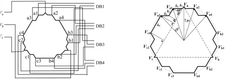
Hence, the phase-shifting angle is 15° among the four sets of three-phase voltages of the 24-pulse rectifier. Two sets of them are displaced at an angle of ±7.5°, with respect to the utility voltage, while the remaining two sets are displaced at an angle of ±22.5°. Consider reference voltage is the three-phase balanced supply voltage (Va, Vb, Vc). Then, the four sets of
three-phase voltages generated by the proposed autotransformer, namely (Va1,Vb1, Vc1),(Va2,
Vb2, Vc2),(Va3, Vb3, Vc3), and (Va4, Vb4, Vc4), are phase shifted +7.5°, -7.5°, +22.5°, and -22.5°,
respectively. To produce symmetrical pulses and to reduce ripples in output voltage, the amplitude of these voltages should be equal. The winding arrangement and phasor diagram of the 24-pulse delta-polygon autotransformer is shown in Figure 3.
Figure 3. Winding arrangement and phasor diagram of the proposed autotransformer
Assume the three-phase supply voltages applied to the autotransformer as:
The four sets of required voltages for the four three-phase diode bridges are:
Then, voltages of phase ‘a’ can be written as:
bc ca a
a V kV kV
V
2 1
1 (8)
bc ab
a
a V kV k V
V
2 1
2 (9)
bc ca a
a V kV k V
V3 1 3 4 (10)
bc ab
a
a V kV k V
V
4 3
2
4 (11)
1 2
2k1k2 k3k4k5 (12)
Substituting Equation (2) to (7) into Equation (8) to (12), the values of k1, k2, k3, k4, and k5 are calculated to be 0.006, 0.073, 0.045, 0.123, and 0.703, respectively.
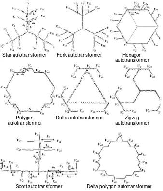
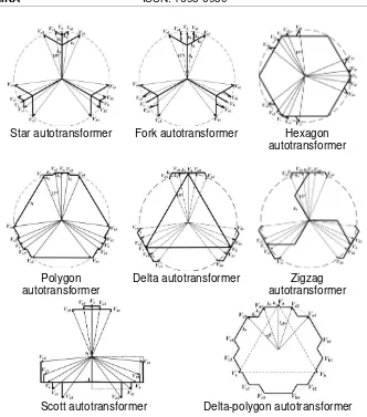
Furthermore, to obtain the optimal autotransformer structure for the 24-pulse rectifier supplying SMPS load, various autotransformer configurations are compared, and their winding arrangements and phasor diagrams are shown in Figure 4 and Figure 5, respectively. The turns ratio of each winding of these autotransformers can also be obtained in a similar way.
Star autotransformer Fork autotransformer Hexagon autotransformer
Polygon autotransformer
Delta autotransformer Zigzag autotransformer
Scott autotransformer Delta-polygon autotransformer
Star autotransformer Fork autotransformer Hexagon autotransformer
Polygon autotransformer
Delta autotransformer Zigzag autotransformer
Scott autotransformer Delta-polygon autotransformer
Figure 5. Phasor diagram of various 24-pulse autotransformers
3. Simulations Based on MATLAB
The MATLAB/Simulink is used to model and simulate 6-, 12-, 18-, and 24-pulse rectifiers, under the same source and load condition. A three-phase 380V, 50Hz AC voltage source is adopted as the power supply. The simulation model of the proposed 24-pulse AC-DC converter based on delta-polygon autotransformer is presented in Figure 6. The source impedance is kept at a practical value of 0.03 pu and the leakage reactance of the autotransformer is set to be 0.05 pu. The simulation results are shown in Figure 7-11 and Table 1-3.
4. Results and Discussion
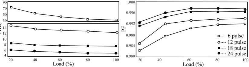
To demonstrate the superiority of the proposed 24-pulse delta-polygon connected autotransformer, various 24-pulse autotransformers are constructed and simulated. Comparison of the kVA rating and power quality indices obtained from various 24-pulse AC-DC converters based on auto-wound transformer is tabulated in Table 1. To exhibit its strong harmonic mitigation ability, performance of the 24-pulse AC-DC converter has been compared with 6-, 12-, and 18- pulse AC-DC converters12-, as shown in Table 2. Moreover12-, the SMPS load of the proposed 24-pulse rectifier has been varied and its effect on various power quality indices is also studied and the results are given in Table 3. Simulated waveforms of supply current/voltage and output current/voltage of the existing 6-pulse rectifier and the proposed 24-pulse rectifier supplying SMPS at full load are shown in Figure 7 and Figure 8, respectively. Figure 9 and Figure 10 depict waveforms of supply current and its harmonic spectrum of the proposed 24-pulse rectifier at light load and under full load, respectively. Additionally, variation of THD of input line current and power factor with load perturbation on the 6-, 12-, 18-, and 24-pulse rectifiers is shown in Figure 11.
It can be observed from Table 1 that the proposed delta-polygon autotransformer based 24-pulse rectifier system lead to the smallest kVA rating and improved PF and THD of utility current as compared to other autotransformer structures. The proposed approach needs an autotransformer of 2.929 kVA (only 19.5% of the output load), resulting in reduced cost and improved efficiency of the whole system. It can also be obtained from Table 1 that the THD of input line current is smaller for the star auto-connected transformer than the proposed delta-polygon connected autotransformer, but the magnetic rating is about 33% higher. Table 2 indicates that, at full load, the THD of supply current of these topologies range from 31.88% to 5.63%, whereas the PF of these converters vary in the range of 0.993 to 0.998.
Table 1. Comparison of magnetic rating and power quality indices for various auto-wound transformer based 24-pulse rectifiers
Transformer type Sr (kVA) K (%) THDi (%) PF
Delta-Polygon 2.925 19.5 4.64 0.998
Modified Scott 4.695 31.3 4.88 0.994
Modified Hexagon 3.180 21.2 5.17 0.991
Modified Polygon 3.255 21.7 5.24 0.995
Modified Zigzag 3.270 21.8 4.68 0.992
Notes: Sr: the magnetic rating of an autotransformer; K (%): percentage of the total output
power; THDi (%): THD of utility current; PF: power factor
the SMPS load and the PF is close to unity at varying load conditions. Therefore, the proposed 24-pulse harmonic mitigator can adhere to the requirements of IEEE Std. 519-1992.
Table 2. Comparison of power quality indices for 6-, 12-, 18-, and 24-pulse rectifiers
TOPO LOGY
THDv (%) THDi (%) Is (A) PF DPF DF
FL FL LL FL LL FL LL FL LL FL LL
6-pulse 9.89 31.88 78.75 21.4 5.5 0.993 0.983 0.999 0.997 0.994 0.986
12-pulse 3.85 12.13 14.91 20.3 5.3 0.996 0.987 0.999 0.998 0.997 0.989
18-pulse 3.91 7.33 8.51 20.0 5.0 0.997 0.991 0.999 0.999 0.997 0.992
24-pulse 3.37 5.63 6.03 19.9 4.9 0.998 0.997 0.999 0.998 0.998 0.998
Notes: THDv (%): THD of utility voltage; Is (A): RMS value of input line current; DF: distortion factor; DPF: displacement power factor; FL: full load; LL: light load.
Table 3. Effect of load variation on power quality parameters of the proposed 24-pulse rectifier
Load (%) THDv (%) THDi (%) Is (A) PF DPF DF
20% 1.31 6.03 4.9 0.997 0.998 0.998
40% 2.06 6.06 8.7 0.997 0.998 0.998
60% 2.53 5.88 12.5 0.998 0.999 0.998
80% 3.12 5.78 16.3 0.998 0.999 0.998
100% 3.37 5.63 19.9 0.998 0.999 0.998
Figure 7. Waveforms of supply current/voltage and output current/voltage of the 6-pulse rectifier supplying SMPS at full load
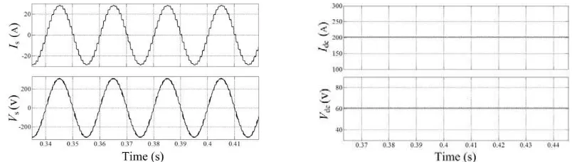
Figure 8. Waveforms of supply current/voltage and output current/voltage of the proposed 24-pulse rectifier supplying SMPS at full load
rectifier system makes power quality indices such as THDi and PF satisfactory for various load
conditions.
Figure 9. Waveforms of supply current and its harmonic spectrum of the proposed 24-pulse rectifier supplying SMPS at light load
Figure 10. Waveforms of supply current and its harmonic spectrum of the proposed 24-pulse rectifier supplying SMPS at full load
Figure 11. Variation of THD of input line current and power quality with load of the 6-, 12-, 18-, and 24-pulse rectifiers
5. Conclusion
Acknowledgements
This project is supported by the Science and Technology Plan Project of Gansu Province (145RJZA098).
Reference
[1] Pressman AI, Billings K, Morey T. Switching Power Supply Design. Third Edition. New York: McGraw-Hill. 2009: 1-3.
[2] IEEE Standard Association. 519-1992. IEEE Recommended Practices and Requirements for Harmonics Control in Electric Power Systems. New York: IEEE Inc.; 1992.
[3] IEC. 61000-3-2. Limits for Harmonic Current Emissions. Geneva: IEC; 2014.
[4] Hanny H Tumbelaka, Lawrence J Borle. Harmonic Mitigation Using a Polarized Ramp-time Current-Controlled Inverter. TELKOMNIKA. 2010; 8(3): 235-244.
[5] Mhawi E, Daniyal H, Sulaiman MH. Advanced Techniques in Harmonic Suppression via Active Power Filter: A Review. International Journal of Power Electronic and Drive System. 2015; 6(2): 185-195. [6] Arivarasu A, Muthukumar K, Balasubramanian R. Closed Loop Non Linear Control of Shunt Hybrid
Power Filter for Harmonics Mitigation in Industrial Distribution System. International Journal of Power Electronic and Drive System. 2014; 5(2): 185-194.
[7] Paice DA. Power Electronic Converter Harmonics: Multipulse Methods for Clean Power. New York: IEEE Press. 1996: 25-30.
[8] Singh B, Gairola S, Singh BN, Chandra A, Al-Haddad K. Multipulse AC-DC Converters for Improving Power Quality: A Review. IEEE Transactions on Power Electronics. 2008; 23(1): 260-281.
[9] Meng F, Yang S, Yang W. Review of Multiple Pulse Wave Rectifier Technology. Electric Power Automation Equipment. 2012; 32(2): 9-22.
[10] Kamath GR, Runyan B, Wood R. A Novel Autotransformer based 18-Pulse Rectifier Circuit. IEEE APEC. Dallas. 2002: 795-801.
[11] Fernandes RC, Oliveira PDS, de Seixas FJM. A Family of Autoconnected Transformers for 12- and 18-Pulse Converters - Generalization for Delta and Wye Topologies. IEEE Transactions on Power Electronics. 2011; 26(7): 2065-2078.
[12] Meng F, Yang W, Yang S. Effect of Voltage Transformation Ratio on the Kilovoltampere Rating of Delta-Connected Autotransformer for 12-Pulse Rectifier System. IEEE Transactions on Industrial Electronics. 2013; 60(9): 3579-3588.
[13] Chen X, Qiu H, Hao C, Li M. Pulse Doubling in AC-DC Converters Based on Zigzag Auto-Connected Transformer for Harmonic Mitigation. International Journal of Electrical Engineering. 2015; 22(1): 9-19.
[14] Chen X, Qiu H. Zigzag Connected Autotransformer-Based 24-pulse AC-DC Converter. International Journal of Emerging Electric Power Systems. 2015; 16(1): 23-32.
[15] Singh B, Gairola S. A 28-Pulse AC-DC Converter for Line Current Harmonic Reduction. IET Power Electronics. 2008; 1(2): 287-295.
[16] Abdollahi R. Design and Construction of A Polygon-Connected Autotransformer-Based 36-Pulse AC-DC Converter for Power Quality Improvement in Retrofit Applications. Bulletin of the Polish Academy of Sciences. 2015; 63(2): 353-362。
[17] Qiu H, Chen X, Lu M. A Delta-Type Autotransformer Based 36-Pulse AC-DC Converter. Australian Journal of Electrical & Electronics Engineering. 2015; 12(1): 13-21.
[18] De Seixas FJM, Barbi I. A 12 KW Three-Phase Low THD Rectifier with High-Frequency Isolation Regulated DC Output. IEEE Transactions on Power Electronics. 2004; 19(2): 371-377.
[19] Kalpana R, Bhuvaneswari G, Singh B, Singh S. Harmonic Mitigator Based on 12-Pulse AC-DC Converter for Switched Mode Power Supply. IET Power Electronics. 2010; 3(6): 947-964.
[20] Singh B, Bhuvaneswari G, Kalpana R. Autoconnected Transformer-Based 18-Pulse AC-DC
Converter for Power Quality Improvement in Switched Mode Power Supplies. IET Power Electronics. 2010; 3(4): 525-541.
[21] Kalpana R, Bhuvaneswari G, Singh B. Autoconnected Transformer-Based 20-Pulse AC-DC